Builders should check this page periodically for new revisions.
Note: Some of these revisions may already be made on your plans, depending upon when your plan set was printed. The Revision Block on each page of your plans details revisions already reflected in your set of plans. For an example revision block and explanation of its use, download the Sonex Drawing System Description plans page (PDF).
Reporting Errors:
Please Contact Sonex Aircraft to notify us of any suspected drawing errors.
Tech Updates Mailing List |
|---|
|
Subscribe to the Sonex Aircraft Technical Updates Mailing List below (part of the Sonex and AeroConversions Web Updates mailing list) for automatic email notification of new drawing revisions, service bulletins and other technical documentation. |
| Sonex Revision Log: | |||||
|---|---|---|---|---|---|
| Date | Drawing | Rev | Location | Incorrect | Correct |
| 10/19/2024 | SNX-B06 | D | -- | -- | Updated to 1220 lbs. Max. Gross Weight for engines 100 HP and above. |
| 10/19/2024 | SNX-B01 | E | Specifications | -- | Updated to 1220 lbs. Max. Gross Weight for engines 100 HP and above. |
| 06/08/2023 | SNX-G02 | B | Detail A and Installation Instructions | O-Ring under nut on exterior of tank. | Install nut without O-Ring. Note: Existing Installations that have an O-Ring under the nut are acceptable if they are not leaking. If there is an exterior O-Ring installed and it leaks, remove the exterior O-Ring. |
| 10/25/2021 | SNX-WC01 | NC | (A-Model to B-Model Wing Conversion) Detail -06L | Pilot holes on narrow flange have gap on wrong end | One pilot hole was move to move the gap. Parts made as previously depicted can still be used by adding a pilot hole in the gap. Download: SNX-WC01-06L_Rev_A.jpeg |
| 09/04/2020 | SNX-P22 | B | -10 | -- | Engineering Revision |
| 01/10/2020 | SNX-L07 | B | Details -07 and -08 | Hole patterns for wheel pant attach plates | Added -08 plate for standard gear aircraft, Modified cut-out for -07 tri-gear plate. Download: SNX-L07-10_Hydraulic_Brake_Wheel_Pant_Bracket.jpg
|
| 03/22/2018 | SNX-P30-BTM | NC | SNX-P40-41 | Bend directions on right side of view. | All bends on right side of view should be opposite those shown on |
| 12/09/2015 | SNX-P17 | NC | -- | -- | Drawing for Horizontal Split Cowling Added to plans set. |
| 12/09/2015 | SNX-P16 | A | -- | -- | Drawing Deleted from Plans set |
| 12/09/2015 | SNX-B03 | M | -- | -- | Drawing SNX-P16 deleted. Reference to installation guides SNX-B10 and SNX-B11 removed. |
| 11/14/2015 | SNX-B03 | L | G02 | — | SNX-G02_A_Fuel Tank Drawing G02, Fuel Tank, removed from plans set. G02 is now provided with the fuel tank. SNX-G02_A_Fuel Tank |
| 10/19/2015 | SNX-G01 | D | — | — | Replaced -08 and -09 Fuel Tank Strap with -10 Fuel tank Strap, Qty. 4. Deleted -07 gascolator Mount brackets. Changed gascolator detail to show Usher-brand gascolator installation (Detail D-D). Added note about optional deletion of gascolator. Download: SNX-G01_E_Fuel_System_Install.pdf |
| 10/19/2015 | SNX-G01 | D | - | - | Replaced -08 and -09 Fuel Tank Strap with -10 Fuel tank Strap, Qty. 4. |
| 10/14/2015 | SNX-G02 | A | — | — | Removed scratch-build detail. Removed pre-molded threaded fittings. Added Oops fitting installation details. Removed felt covering required for scratch-built aluminum tanks. Removed drawing from Sonex plans set. Drawing now included with each fuel tank. Download: SNX-G02_A_Fuel_Tank.pdf |
| 06/25/2015 | SNX-W21 | B | -01L/R Assemblies | — | Added -12 Aileron Drive Rib references for kit builders. |
| 06/25/2015 | SNX-W17 | A | -01R/L | — | Added note that Plans Builders must modify W16-06 Ribs, as always, to make root ribs and kit builders are supplied the root ribs pre-finished (W16-10 and W16-11). |
| 06/25/2015 | SNX-W16 | C | Detail -12 | — | Created Detail -12 Aileron Drive Rib callout – Applies only to kit builders who were supplied pre-finished parts. |
| 06/23/2015 | SNX-F26 | D | — | — | Added Machined Fuselage Splice Plates (parts -09R/L and -10R/L), to kits replacing parts -04R/L, -05R/L, -06R/L and -07R/L. Plans builders may still build those parts, or purchase the new -09R/L and -10R/L parts. |
| 03/23/2015 | SNX-F16 | — | Part -02 | Drawing is correct, Sonex-provided matched-hole part provided before 04/2015 may have extra holes. | DO NOT transfer the 2 pilot holes shown in the accompanying photograph to the forward fuselage verticals. These two holes in F16-02 are to be ignored. Transferring them may negatively impact your final wing-spar holes. Download: F16-02-Errant-Hole.jpg |
| 02/04/2015 | SNX-L03 | D | — | — | Removed -04 and -05 tail wheel weldments (Discontinued parts). Removed -01 Tail Wheel Installation (Obsolete). Removed -27 Tailwheel Installation detail and incorporated it into -28 |
| 02/03/2015 | SNX-L03 | D | — | — | Drawing Update – Tailwheel Upgrade Removed -04 and -05 tail wheel weldments (Discontinued). Removed -01 Tail Wheel Installation (Obsolete), replaced by -28 Removed -27 4″ Tailwheel Installation and incorporated it into -28 Installation. |
| 03/18/2014 | SNX-W21 | A | -01L Assembly | Clip attachment location shown too near to wing rib. | Shifted -09 Clips outboard so Kit Supplied Parts would match holes provided in the vertical channels. The space between the wing rib flange and the clip is 13/64″ [5.16mm]. Added “R” and “L” to Forward and Aft Vertical Channels to match supplied parts. |
| 01/21/2014 | SNX-C06 | A | -06 and -07 Assemblies | CCP-42 Rivets on -07 | CCP-44 Rivets on -07. Part dimensions reformatted for easier interpretation. |
| 01/21/2014 | SNX-W17 | NC | -01R/L | — | Changed Forward Root Rib Labels from SNX-W15-05 Forward Wing Rib to SNX-W15-08 (RH) and SNX-W15-09 (LH) Changed Aft Root Rib Labels from SNX-W16-06 Aft Wing Rib to SNX- W16-10 (RH) and SNX-W16-11 (LH) |
| 01/21/2014 | SNX-W16 | B | Details -10 and -11 | — | Created Details -10 and -11 RH and LH Aft Root Rib Details (Use Full Size Patterns on SNX- W17) |
| 01/21/2014 | SNX-W15 | C | Details -08 and -09 | — | Created Details -08 and -08 for RH and LH forward root ribs. (Note: This detail is also on SNX- W17-01R/-01L Root Rib Installations) |
| 01/21/2014 | SNX-T13 | NC | Detail -07 | 3/32″ Pilot Holes Typical 36 Places | 3/32″ Pilot Holes Typical 41 Places |
| 12/04/2013 | SNX-B03 | K | SNX-B07 | — | SNX-B07 Builder’s Guide removed from drawing tree. This is no longer supplied with the plans. |
| 11/01/2013 | SNX-T07 | C | Next Assembly Block | Next Assembly for -04L and -04R listed as T02 | Next Assembly for -04L and -04R listed is T06 |
| 10/21/2013 | SNX-L06 | B | -02 and -04 Installation and Details -06 and – 17 | — | Changes for new “Flat Sided” Nose Wheel Pant which eliminates the -17 Nose Pant Attach Bracket: -02 Tri-Gear Installation: Modified front view to show flat sides. -04 Wheel Pant Installation: Deleted -17 and associated hardware. Detail -06: Modified top view to show flat sides. Detail -17: Deleted Bracket Mount Detail. No Longer Required. Download: SNX-L06_04_Detail_F.jpg |
| 10/15/2013 | SNX-G01 | C | View E | — | Added AN819-4D Sleeve |
| 09/09/2013 | SNX-G01 | B | View E | N816-4-4D | AN816-4D |
| 09/09/2013 | SNX-B03 | J | SNX-C10 thru -C12 | SNX-C10, SNX-C11, and SNX-C12 do not exist | Removed SNX-C10, SNX-C11, and SNX-C12 Optional Sport Arcro Competition Mods from Drawing Tree. |
| 09/09/2013 | SNX-L03 | C | Details -20, -30, -27 and -28 | — | Added -20 and -30 (4″ and 6″) Machined Tailwheel Assemblies and Added – 27 and -28 (4″ and 6″) Machined Tailwheel Installations. |
| 04/01/2013 | SNX-L07 | NC | Detail -08R/-08L | Qty 3 AN-3 Bolts called out attaching hydraulic brake body to wheel pant mount plate | Qty 1 Clevis Pin (1/4″ diameter) replaces these 3 bolts. Qty 1EA MS20392-3C49 Clevis Pin, AN960-416 Washer, and MS24665-134 Cotter Pin. Locate hole in Brake Back Plate per hole in Main Brake Body, Wheel Pant Mount Plate, and Axle Tab. Download: SNX-L07_A_Optional_Hydaulic_Brake_Installation.pdf |
| 02/19/2013 | SNX-F12 | C | General Construction Order | General Constructions steps 21 and 27 refer to a deleted fresh air vent. | Delete General Constructions steps 21 and 27 referring to fresh air vent. Download: SNX-F12D.pdf |
| 12/02/2012 | SNX-D01 | A | Section D-D | — | Add AN365-832A Nut, 5 Req’d on -02 |
| 08/24/2011 | SNX-P22 | A | -09 and -10 Engine Mounts | — | Added -07 Additional Lower Cross Tube. See Service Bulletin SNX-SB-007: SNX-SB-007-TRI-3300_Motor_Mount_Change.pdf |
| 07/13/2011 | SNX-L01 | A | — | Note: Do not allow cad plated tools or hardware to contact titanium gear legs. | Removed note. |
| 07/11/2011 | SNX-L03 | B | Detail -05 | — | Drive plate thickness increased from .090 to .125″ for universal |
| 07/11/2011 | SNX-L03 | A | Detail -05 | Width of Caster Opening | 3/4″ should be 13/16″. 1-1/2″ should be 1-5/8″ |
| 07/11/2011 | SNX-L03 | A | -01 Tail Wheel Install | AN4C-12A Bolt (Qty. 2) AB365-428 Nut (Qty. 2) | AN4-12 Bolt (Qty. 2), AN310-4 Castle Nut (Qty. 2) and MS24665-208 Cotter Pin (Qty. 2) |
| 07/11/2011 | SNX-L03 | A | — | Note: Do not allow cad plated tools or hardware to contact titanium gear legs. | Removed note |
| 06/28/2011 | SNX-L03 | A | -01 Tail Wheel Installation | AN4C-12 Bolt and AN365-428 Nut | Replace with AN4-12 Bolt, AN310-4 Castle Nut, and MS24665-208 Cotter Pin |
| 06/28/2011 | SNX-L01 | NC | -01 Standard Gear Installation | AN4C-30 Bolt and AN365-428 Nut | Replace with AN4-30 Bolt, AN310-4 Castle Nut, and MS24665-208 Cotter Pin |
| 06/28/2011 | SNX-L01 | NC | Detail A and -02 Tri Gear Installation | AN4C-17 Bolt and AN365-428 Nut | Replace with AN4-17 Bolt, AN310-4 Castle Nut, and MS24665-208 Cotter Pin |
| 05/11/2011 | SNX-F22 | A | Detail -03 | Missing the dimension from left edge of part to the first of 8 holes. | Added 2-27/32″ dimension. |
| 03/24/2011 | SNX-B03 | H | SNX-T14 | SNX-T14 Optional Tail Tip Installation | SNX-T14 Tail Tip Installation |
| 03/24/2011 | SNX-T14 | NC | Detail A | — | Install CCP-42 rivets to secure tail tips |
| 03/24/2011 | SNX-T08 | NC | Next Assembly Block | Next Assembly for -01 was SNX-T01 | Next Assembly for -01 should be SNX-T14 |
| 03/24/2011 | SNX-T08 | NC | -01 | Installing rivets through skins and T10-04 tip ribs. | Rivets through tip ribs not installed at this time. Rivets are installed on SNX-T14. |
| 03/24/2011 | SNX-T02 | B | Next Assembly Block | Next Assembly has no entry | Next Assembly should be SNX-T14 |
| 03/24/2011 | SNX-T02 | B | -02 | Installing rivets through skins and T04-05 tip ribs. | Rivets through tip ribs not installed at this time. Rivets are installed on SNX-T14. |
| 03/24/2011 | SNX-T02 ** | B | Section B-B | — | Trim Tab not required if Dial-A-Speed trim (AeroConversions Trim System) is installed. |
| 03/24/2011 | SNX-T01 | A | -01 and -03 | Fiberglass tips not depicted | Added fiberglass tips |
| 03/23/2011 | SNX-E01 | A | — | — | Revised schematic to eliminate wiring for specific equipment. Added panel size and depth details to aide panel planning. Download new drawing: SNX-E01B.pdf |
| 03/02/2011 | SNX-W21 | NC | -12 Bushings | “Epoxy Prime” | “Lubricate with White Lithium Grease” |
| 03/02/2011 | SNX-W21 | NC | -11 Bellcrank | Hole Diameter missing | 3/16″ diameter holes, 3 places. |
| 03/02/2011 | SNX-W21 | NC | -10 Bellcrank Assembly | — | Added note to tighten nut to lock bushings against bellcrank. |
| 02/17/2011 | SNX-T03 | NC | -05 Assembly | SNX-T06-03 incorrectly depicted with solid line on rear view | SNX-T06-03 correctly depicted with hidden line on rear view |
| 02/15/2011 | SNX-F02 | A | Construction Order | — | Added Step 16, “Drill 1/4″ through Rear Spar Carry Through Assembly” |
| 02/04/2011 | SNX-F03 | B | Details -02, -03, -05L, -05R, and -01 Assembly | 1/4″ Diameter Holes | 3/16″ Diameter Holes |
| 01/10/2011 | SNX-C07 | NC | View A-A, View C-C, and Construction Order | Callout for SNX-F10-02 Angle | Callout for SNX-C06-05 Angle |
| 01/10/2011 | SNX-C07 | NC | -02 Assembly | Callout for SNX-F10-02 Angle | Callout for SNX-C06-05 Angle |
| 01/10/2011 | SNX-C06 | NC | Section H-H | — | Corrected Quantity of hardware needed from 8 to 6, and from 16 to 12. |
| 01/10/2011 | SNX-C06 | NC | -06 Angle | Make from SNX-Z02-03 | Make from 1/8″x1″ 6061-T6 Aluminum Angle Extrusion |
| 01/10/2011 | SNX-C06 | NC | Detail H-H | -11 Control Pushrod Cover Reference | -08 Control Pushrod Cover Reference |
| 09/14/2010 | SNX-F24 | NC | Detail -01 | — | Increase size of note to keep cross tie box square, not twisted. |
| 09/14/2010 | SNX-F21 | B | Section P-P | — | Added dimensions to locate SNX-F23-09 at 16-9/32″ for lowered seat option. |
| 09/14/2010 | SNX-F21 | B | Section N-N | — | Added dimensions to locate SNX-F23-11 at 8-7/8″ for lowered seat option. |
| 09/14/2010 | SNX-F21 | B | Detail -01 | — | Added note to rivet lower skin only after wings and tail are rigged. |
| 09/14/2010 | SNX-F20 | NC | Detail -05 | — | Lengthened lower flange from 21/32″ to 25/32″ to provide more leeway during installation. |
| 09/14/2010 | SNX-F19 | NC | Detail C | Drawing Correction | Removed depiction of 2 screws installed on later assembly. |
| 09/14/2010 | SNX-F16 | D | Detail -03 | — | Added note about additional fasteners added to assembly depending on gear configuration. Reference SNX-F01. |
| 09/14/2010 | SNX-F15 | NC | Detail -13 | — | Vent Door Latch Deleted. |
| 09/14/2010 | SNX-F14 | D | Detail -13R | End view incorrect | Moved end view from LH side to RH side |
| 09/14/2010 | SNX-F13 | A | -02R and -02L | — | Clarified slots are in -02L ONLY |
| 09/14/2010 | SNX-F13 | A | Details -01, -07, Detail A | — | Deleted -07 Vent Door, Detail A, and Vent depiction in Detail -01 |
| 01/28/2010 | SNX-W03 | D | Detail -03 Hinge Half | Detail -03 Hinge Half | Should be: Detail -02 Hinge Half |
| 12/18/2009 | SNX-F25 | D | -01L and -01R | — | Use CCP-46 rivets instead of CCC-46 rivets to attach F26-08 Rudder Stop |
| 12/04/2009 | SNX-C09 | A | — | — | Sport Trainer (ST) Modification for Dual Stick Sonex or Waiex: SNX-C09_OptionalCenterControls_A.pdf Replaced C09-11 Flap and Brake Mount with CO9-19 Flap and Brake Mount and C09-10 Support Angle with C09-20 Support Angle |
| 12/04/2009 | SNX-C08 | A | — | — | Sport Trainer (ST) Modification for Dual Stick Sonex or Waiex: SNX-C08_OptionalCenterControls_A.pdfReplaced C09-11 Flap and Brake Mount with CO9-19 Flap and Brake Mount and C09-10 Support Angle with C09-20 Support Angle |
| 12/04/2009 | SNX-C08 | — | — | — | Sport Trainer (ST) Modification for your Dual-Stick Equipped Sonex or Waiex: |
| 10/02/2009 | SNX-P30 | A | Detail B-B | Throttle and Mixture cable call-outs incorrect | Refer to engine and/or Aerocarb manual for proper throttle cable options. |
| 10/02/2009 | SNX-P20 | B | Detail B-B | Throttle and Mixture cable call-outs incorrect | Refer to engine and/or Aerocarb manual for proper throttle cable options. |
| 10/02/2009 | SNX-P10 | A | Detail B-B | Throttle and Mixture cable call-outs incorrect | Refer to engine and/or Aerocarb manual for proper throttle cable options. |
| 09/28/2009 | SNX-F13 | NC | Detail -01 | Missing dimension for upper, forward-most 11/64″ dia. hole | Missing dimension is 11/16″ |
| 09/03/2009 | SNX-G01 | B | -05 Tank Assembly | 1/4″ Pipe Thread Brass Close Union (Automotive) | AN911-2D Nipple |
| 09/03/2009 | SNX-T09 | NC | Section A-A | Main Spar Forward Strap incorrectly labeled “SNX-T12-01” | SNX-T12-02 Main Spar Forward Strap |
| 07/15/2009 | SNX-F03 | A | -02 Channel | — | Added 1-3/4″ hole location for drop seat option. |
| 07/15/2009 | SNX-F02 | NC | Section E-E | — | Added note to pilot drill wing mounting holes from 1/4″ to 3/8″ Dia. using |
| 07/14/2009 | SNX-C06 | NC | Detail -06 | Make from SNX-Z02-03 Angle Stock | Make from 1″ x 1″ x 1/8″ 6061-T6 extrusion.Note: the depiction is correct but the material call-out is incorrect. |
| 02/25/2009 | SNX-T07 | B | Detail -05 Trim Tab | MS20257P1 Hinge | MS20257P3 Hinge |
| 02/16/2009 | SNX-C02 | E | -04 Push Rod Assembly | — | Note: An Aurora MW-5 Rod End Bearing with a 3/16″ I.D. x 5/16″ O.D. x 3/8″ Long Sintered Bronze Bushing (SYMMCO # SS-610-6 or equal) to bush down to 3/16″ inside diameter may be substituted for the MW-3M-16 |
| 02/06/2009 | SNX-F17 | NC | Detail -02 | — | Drawing is correct. Adjust flutes in firewall as needed to install Southco fasteners. See photo: Southcos-Installed.jpg |
| 01/06/2009 | SNX-W25 | NC | Detail of Aileron Balancing | Delete this Detail | Balance Sport Acro Aileron with 1/2 of the supplied Counterweight (Sonex P/N SNX-W04-08). All flight testing has been conducted using the same counterweight as the standard Sonex Aileron. |
| 11/12/2008 | SNX-C09 | NC | — | — | Sport Trainer (ST) Modification for Dual Stick Sonex or Waiex: SNX-C09_OptionalCenterDetails_NC.pdf General Warning: Do not install the ST modifications until the wing is installed in the wing spar box. |
| 11/12/2008 | SNX-C08 | NC | — | — | Sport Trainer (ST) Modification for Dual Stick Sonex or Waiex: SNX-C08_OptionalCenterControls_NC.pdf General Warning: Do not install the ST modifications until the wing is installed in the wing spar box. |
| 11/12/2008 | SNX-C07 | NC | — | — | Lowered Seat Modification Drawing Created: SNX-C07-LowSeat-LowCabin.pdf |
| 11/12/2008 | SNX-C06 | NC | — | — | Lowered Seat Modification Drawing Created: SNX-C06-LowSeat.pdf |
| 11/12/2008 | SNX-B03 | G | Drawings SNX-C06, SNX-C07, SNX-C08, SNX-C09, SNX-W24, SNX-W25, SNX-W26, SNX-W27. | — | Updated Drawing Tree to show Lowered Seat Modification, Sport Trainer (ST) Modification, and Sport Acro Modification. |
| 11/12/2008 | SNX-W24, 25, 26, 27 | NC | — | — | Optional Sport Acro Aileron Installation: If not included in your plans, these drawings are available upon request: tech@sonexaircraft.com |
| 11/01/2008 | SNX-C06 | — | — | — | Lowered Seat Modification for Dual-Stick Sonex: |
| 08/12/2008 | SNX-W08 | C | Details A and E | 2 rivets securing SNX-W11-06 not identified | Replaced rivets with bolts and screws as shown on linked files: SNXW08c-Detail-A.jpg; SNXW08c-Detail-E.jpg |
| 06/26/2008 | SNX-F23 | B | -09 Assembly and -11 Assembly | 1″OD x 7/8 ID Plastic Bushing | 1-1/8″ OD x 7/8″ ID Plastic Bushing (Heyco 2163 or equivalent) |
| 06/26/2008 | SNX-F23 | B | -10 Channel and -12 Channel | 1″ diameter hole | 1-1/8″ Diameter hole |
| 10/31/2007 | SNX-B03 | NC | SNX-B10 and SNX-B11 drawings. | — | Remove from Drawing Tree. These documents are supplemental manuals, not included in the Sonex plans, that ship with your AeroVee or Jabiru engine purchase from Sonex Aircraft, LLC. |
| 10/10/2007 | SNX-B10 | D | Oil Cooler Installation, pages 3, 4, and 12 | Leave Blank | Jabiru Engines with hydraulic lifters must use an AeroClassic 800075 Oil Cooler to avoid interference with the exhaust system. |
| 10/04/2007 | SNX-W13 | NC | -02R/L | Drawing Error only- Bottom View is not properly depicted | All dimensions are correct. Bottom view should show sides extending beyond the bottom flange. |
| 10/04/2007 | SNX-W10 | B | Detail B | 2nd hole down on LH Side not dimensioned (appears to be 5/8″) | Locate 2nd hole down (fuselage attach hole) is 37/64″ [14.58mm] from the left edge. |
| 10/04/2007 | SNX-P13 | C | Detail -13 Hinge Half | 4 1/2″ Long | 3 1/2″ Long |
| 10/04/2007 | SNX-L02 | NC | Detail -08 | — | Bushing SNX-L02-08 Supplied in kits may be 1/4″ too long. Trim bushing to fit. |
| 03/28/2007 | SNX-L02 | NC | -08 Axle Bushing | Some kit-supplied bushings are 4.5″ long. | Trim bushing to 4.25″ long. |
| 02/12/2007 | SNX-G02 | NC | General Notes | — | Add Note: Rotationally Molded Tank Standard. Aluminum tank option shown |
| 02/12/2007 | SNX-G01** | B | Detail -08 and -09 Straps | — | Note: Straps may be substituted with 3/4″ wide x 0.125″ thick 6061-T6 Aluminum. Note: SNX-G01-10 universal Fuel Tank Straps now provided with kits. |
| 02/12/2007 | SNX-F21 | B | Detail D | Cherry CCP-42 Blind Rivets 8 req’d on -01 | Cherry CCP-44 Blind Rivets 8 req’d on -01 |
| 02/12/2007 | SNX-F21 | B | Section K-K | Locate per Pilot Holes in Bulkhead | Locate per Pilot Holes in the lower angle |
| 02/12/2007 | SNX-F11 | B | Detail S | Callout for AN470AD-4-5 IS NOT AN ERROR | Install Rivet so Factory Head is in the cockpit. Rivet is driven into the c’sink inside the spar box. |
| 02/12/2007 | SNX-F10 | A | Detail -03 (SNX-SB-003) | Make from SNX-Z02-03 Angle Stock | Make from 1″x1″x1/8″ thick 6061-T6 Angle |
| 02/12/2007 | SNX-D01 | C | Detail R | — | CANOPY LOCK PIN IS OF CRITICAL IMPORTANCE! This Lock Pin MUST be installed for all flights. |
| 02/12/2007 | SNX-C02 | E | -04 Push Rod Assembly | Compression Spring, 2 Required on -04 | Assigned Part Number SNX-C02-10 to this Spring |
| 02/12/2007 | SNX-C01 | B | -01 Installation | Flap Drive Pivot Blocks installed with AN4 Bolts | Install Flap Drive Pivot Blocks with AN3 Bolts and associated hardware. |
| 02/12/2007 | SNX-W23 | NC | View of Bottom of RH Wing | 3/8″ O.D. x 1/4″ I.D. x 66″ [168mm] Long Tygon Tubing | 3/8″ O.D. x 1/4″ I.D. x 66″ [1677mm] Long Tygon Tubing |
| 02/12/2007 | SNX-W16 | A | Detail -07, -08 | — | Replace Gusset Stock Blanks with laser-cut blanks SNX-W16-07 and SNX-W16-08 |
| 02/12/2007 | SNX-W15 | B | Details -01, -02, -03, -04, -06 | — | Kit Builders Modify -06 view to use laser-cut Gusset Stock SNX-W15-08 on top and bottom. |
| 02/12/2007 | SNX-W15 | B | Detail -08, -09 | — | Replace Gusset Stock Blank Size w/Laser-Cut Gusset Stock SNX-W15-08 |
| 02/12/2007 | SNX-W11 | A | -01 Lower Angle | — | Add Overall Dimension of 23 5/32″ |
| 02/12/2007 | SNX-W08 | B | Detail E | AN3-7A Bolt…Install from Forward Side | AN3-7A Bolt…Install from Aft Side. See linked file: SNXW08c-Detail-E.jpg |
| 02/12/2007 | SNX-W07 | A | -01R/L | — | Add Note: Drill holes in leading edges for CCC-42 with a #32 Drill then dimple |
| 02/12/2007 | SNX-W07 | A | -01R/L | — | Add Note: Building a flat wing is critical in this procedure. Ref the Wing Squaring/Skinning Instructions Located on our Instruction Sheets Page |
| 02/12/2007 | SNX-T14 | NC | General Note | — | Remove Optional from Title Block and all notes |
| 02/12/2007 | SNX-T12 | NC | Detail -01 | 3/32″ Pilot Holes Typical 40 places | 3/32″ Pilot Holes Typical 38 places |
| 02/12/2007 | SNX-T10 | NC | Detail -04 Tib Rib | — | If fiberglass tail tips are installed, remove the tab on the leading edge before installing. |
| 02/12/2007 | SNX-T04 | NC | Detail -05 Tip Rib | — | If fiberglass tail tips are installed, remove the tab on the leading edge before installing. |
| 02/12/2007 | SNX-T02 | B | Section E-E | 9 Spaces @ 1 1/16″ [25.3 mm] | 9 Spaces @ 1 1/16″ [27.0 mm] Center to Center Spacing |
| 02/12/2007 | SNX-P32 | NC | -01 Motor Mount Installation | AN960-4 Washer 8 Required on -01 | AN960-416 Washer 8 Required on -01 |
| 02/12/2007 | SNX-P31 | A | -01 Motor Mount Installation | AN960-4 Washer 8 Required on -01 | AN960-416 Washer 8 Required on -01 |
| 02/12/2007 | SNX-P30 | A | Detail A | Automotive Shock Absorber NAPA #650-1151 | ACV-P01-19 Rubber Shock Mounts |
| 02/12/2007 | SNX-P22 | NC | -01 Motor Mount Installation | AN960-4 Washer 8 Required on -01 | AN960-416 Washer 8 Required on -01 |
| 02/12/2007 | SNX-P21 | B | -01 Motor Mount Installation | AN960-4 Washer 8 Required on -01 | AN960-416 Washer 8 Required on -01 |
| 02/12/2007 | SNX-P20 | A | Detail A | “…Engine Mount Cushion Set Supplied with Jabiru Engine” | “…ACV-J01-10 Shock Mounts for Jabiru Engine” |
| 02/12/2007 | SNX-P16 | A | Detail -02 | — | Delete -02 Cowling w/bumps, replace with -03 Universal Cowling |
| 02/12/2007 | SNX-P12 | B | -01 Motor Mount Installation | AN960-4 Washer 8 Required on -01 | AN960-416 Washer 8 Required on -01 |
| 02/12/2007 | SNX-P11 | B | -01 Motor Mount Installation | AN960-4 Washer 8 Required on -01 | AN960-416 Washer 8 Required on -01 |
| 02/12/2007 | SNX-P10 | A | Detail A | “…Engine Mount Cushion Set Supplied with Jabiru Engine” | “…ACV-J01-10 Shock Mounts for Jabiru Engine” |
| 02/12/2007 | SNX-L02 | NC | -01 Installation | Helical Compression Spring, 1 Required on -01 | Assigned Part Number SNX-L02-12 to this Spring |
| 02/12/2007 | SNX-L01 | NC | -05 Axle | Do not drill 5/32″ Cotter Pin Hole located 1 1/8″ from end | Drill this 5/32″ Hole and locate once wheel and brake assembly are installed |
| 12/06/2004 | SNX-G01 | B | -05 Tank Install | 1/8″ Felt Strips | Note: Felt Strips optional with Sonex RM (plastic) fuel tank. |
| 12/06/2004 | SNX-F25 | NC | Detail P | SNX-F26-05R, -05L | SNX-F26-07R, -07L |
| 12/06/2004 | SNX-F23 | A | Detail -12 Aft Support Channel | -12 Support Angle | -13 Support Angle |
| 12/06/2004 | SNX-F11 | B | View N-N | F16-12 Aft Clip | F17-12 Aft Clip |
| 12/06/2004 | SNX-D02 | C | Detail -20 | — | Swedged Canopy Cable available from Sonex Aircraft, LLC |
| 12/06/2004 | SNX-B10 | NC | Page 13 | Do not cut Baffles for 2200 per these dimensions | Cut Baffles leaving 1″ extra material. Trim as required to fit. |
| 12/06/2004 | SNX-B10 | NC | Page 10 | — | Added use of Locktite 243 to Step #2 |
| 12/06/2004 | SNX-B10 | NC | Page 4 “Jegs” | 799-610020 Qty 3 | 799-610020 Qty 4 |
| 12/06/2004 | SNX-B10 | NC | Page 4 “Wicks” | AN816-6D Qty 4 | AN816-6D Qty 3 |
| 12/06/2004 | SNX-B10 | NC | Page 4 “Wicks” | — | Add AN816-6-2D Qty 1 |
| 12/06/2004 | SNX-B10 | NC | Page 4 “Wicks” | MS20822-6D | MS20822-6-6D |
| 12/06/2004 | SNX-B10 | NC | Page 3 “Cockpit Controls” | — | Add Rod End for Throttle Cable |
| 12/06/2004 | SNX-B10 | NC | Page 3 “Fuel System Installation” | — | Add AN816-6-2D Qty 1 |
| 12/06/2004 | SNX-B10 | NC | Page 3 “Fuel System Installation” | AN816-6D Qty 2 | AN816-6D Qty 1 |
| 12/06/2004 | SNX-B10 | NC | Page 3 “Oil Cooler Installation” | 799-613160 Qty 2 | 799-613160 Qty 1 |
| 12/06/2004 | SNX-B10 | NC | Page 3 “Oil Cooler Installation” | 799-610020 Qty 2 | 799-610020 Qty 3 |
| 12/06/2004 | SNX-B10 | NC | Page 3 “Oil Cooler Installation” | MS20822-6D | MS20822-6-6D |
| 12/06/2004 | SNX-W12 | C | -02R/L, -03R/L | — | Add note for kit builders: Pilot holes for rib attach points must be drilled accurately. Use a formed rib as a pattern. |
| 12/06/2004 | SNX-Z01 | A | -03 Angle usage table | SNX-F10 Qty 40″ | Delete call out for SNX-F10 Qty 40″ |
| 12/06/2004 | SNX-W23 | NC | Detail -04 | — | Premade Pitot-static assembly available as an alternative from Aircraft Spruce, P/N 15144. |
| 12/06/2004 | SNX-W12 | C | Details D and G | AN3-7, 2 places | AN3-7A, 2 places |
| 12/06/2004 | SNX-W12 | C | -02R/L, -03R/L | — | Add note for kit builders: Pilot holes for rib attach points must be drilled accurately. Use a formed rib as a pattern. |
| 12/06/2004 | SNX-W05 | NC | -01R/L | 4 pilot holes on one W06-02 Rib Installation | 4 Pilot holes should be shown as 4 rivets installed |
| 12/06/2004 | SNX-W02 | NC | Detail F | File/Sand Thrust Bearing Thickness as required | File/Sand Flanged Bearing length as required. |
| 12/06/2004 | SNX-L01** | NC | -09 Assembly | — | Note: Optional Machined Brake Drum: ACV-W01-10 may be substituted for the Azusa Brake Drum. |
| 12/10/2003 | SNX-P20 | — | Detail -04 Fin Installation | — | Add Fin to 3300 Tri-Gear Wheel Pant per this drawing: SNXP20b.pdf |
| 12/01/2003 | SNX-F27 | B | -09 Fairlead Assembly | -07 Fairlead Mount Weldment | -10 Fairlead Mount Block |
| 12/01/2003 | SNX-F23 | NC | -08 Fitting | — | Add 1/2″ to Tab on fitting to allow for easier Seat Belt attach. |
| 12/01/2003 | SNX-F14 | C | -13R/-13L | 7 Spaces @ 15/16″ | 5 Spaces @ 15/16″ |
| 12/01/2003 | SNX-F14 | C | -08R/L | Incorrect Side View | Extend side view to match front view |
| 12/01/2003 | SNX-F13 | NC | -03 R/L | — | Add 3/16″ Hole Call-out to side view |
| 12/01/2003 | SNX-F01 | A | Detail B | Drill, Countersink: CCP-44 | Dril, Countersink: CCC-44 |
| 12/01/2003 | SNX-E01 | NC | Rev A Drawing Released | — | Current Stratomaster and Optional Lighting Wiring Diagram. |
| 12/01/2003 | SNX-E01 | NC | Electrial Wiring Diagram | 4 gauge wire routed from starter to relay | 20 gauge wire |
| 12/01/2003 | SNX-E01 | NC | Electrial Wiring Diagram | 8 gauge wire routed from Main Bus to Alternator | Route 8 gauge from Alternator directly to Battery |
| 12/01/2003 | SNX-D02 | B | Detail -03 | 55 1/8″ Long | 56 7/8″ Long |
| 12/01/2003 | SNX-D01 | B | -01 Canopy Install | — | Add Machine Screw option to attaching side rails |
| 12/01/2003 | SNX-C05 | C | -01 Dual Stick Assembly | AN3-14 Bolt 2 Req’d | AN3-5 Bolt 2 Req’d |
| 12/01/2003 | SNX-C02 | D | -03R/-03L | — | Add length as req’d to reach rudder horn. |
| 12/01/2003 | SNX-B04 | A | TAIL VIEW | — | Option: Add Rudder Trim Tab- VW Lower RH 1.5″Wx6″ L |
| 12/01/2003 | SNX-W12 | B | -02R/L, -03R/L | SNX-Z01-01 | SNX-Z01-02 |
| 12/01/2003 | SNX-T13 | NC | Rudder Skin | Solid Line on main (Left Side) View | Dashed (Phantom) Line on Main (Left Side) View |
| 12/01/2003 | SNX-P31 | NC | -01 Motor Mount Installation | — | Remove Material from F15-02R/L to clear motor mount. |
| 12/01/2003 | SNX-P21 | A | -01 Motor Mount Installation | — | Remove Material from F15-02R/L to clear motor mount. |
| 12/01/2003 | SNX-P20 | A | -01 and -02 installations | Earl’s Cooler 21903 | B&M Cooler 130-70265 (www.jegs.com) |
| 12/01/2003 | SNX-P11 | A | -01 Motor Mount Installation | — | Remove Material from F15-02R/L to clear motor mount. |
| 12/01/2003 | SNX-P01 | NC | Engine Package Weights | 131 Jab 2200, 161 Jab 3300 | 140 Jab 2200, 170 Jab 3300 |
| 12/01/2003 | SNX-L04 | A | Detail E | — | Optional: Replace AN525-416R28 with AN4-16A Bolts. |
| 11/21/2003 | SNX-G01 | A | -05 Tank Assembly, View A-A, Fuel System Schematic | — | Revised to show Electronic Fuel Level Probe (Sight gauge shown as optional). |
| 12/02/2002 | SNX-F21 | B | Section K-K | F22-02 Bulkhead | F23-02 Bulkhead |
| 12/02/2002 | SNX-F16 | C | Detail -02 | — | Top View doesn’t show 1/4″ x 1″ cutout |
| 12/02/2002 | SNX-F16 | C | Detail -02 | — | 3/16″ Dimension Line is shifted to the right. |
| 12/02/2002 | SNX-F10 | NC | Detail -19 | AN3-10A Bolts | AN3-7A Bolts |
| 12/02/2002 | SNX-D01 | A | -04 hook rail assy | — | Add AN365-832A Nut, 2 Req’d on -04 |
| 12/02/2002 | SNX-W03 | D | Assembly -03 | Rib Call-out W04-02 and W04-03 are Reversed | — |
| 12/02/2002 | SNX-W03 | D | Detail -01R, -01L | Center Rib Call-out, W04-03 and W04-02 are Reversed | — |
| 12/02/2002 | SNX-T06 | — | Detail -02 | CCP-42 Flush Blind Rivets 14 req’d and 17 req’d | CCP-42 Blind Rivets 14 req’d and 17 req’d |
| 12/02/2002 | SNX-P31 | NC | Detail -01 | Isometric shows cross-tubes to lower mounts | 3-View shows cross-tubes to upper mounts. This is correct. |
| 10/29/2001 | SNX-L03 | NC | -01 Tail Wheel | MS20392-3C9 and MS20392-3C11 Clevis Pins | Replaced with AN23-10 and AN23-11 Clevis Bolt and AN310-3 Castle Nuts. |
| 10/26/2001 | SNX-L03 | — | Detail -01 Rudder Horn/Push Rod | MS20392-3C9 Clevis Pin , 1 Req’d | AN23-12 Clevis Bolt, 1 Req’d |
| 10/26/2001 | SNX-L03 | — | Detail -01 Caster/Push Rod | MS20392-3C9 Clevis Pin , 1 Req’d | AN23-10 Clevis Bolt, 1 Req’d |
| 06/10/2001 | SNX-G01** | NC | -03 and -04 Fuel Tank Straps | -03 and -04 Fuel Tank Straps | Made fuel straps two pieces. Deleted part numbers -03 and -04 and replaced with -08 (Qty 2) and -09 (Qty 2). Note: SNX-G01-10 universal Fuel Tank Straps now provided with kits. |
| 06/10/2001 | SNX-D02 | A | -04 and -06 Canopy Bows | Make from Square Tubing | Make from Round Tubing |
| 06/08/2001 | SNX-C03 | B | Detail -05 | 3/4″D x 0.035″ Wall 4130 12 3/4″ Long | 3/4″D x 0.035″ Wall 4130 14 3/8″ Long |
| 06/08/2001 | SNX-B06 | NC | Page 30 | Maneuvering Speed: 136 MPH | Maneuvering Speed (Va): 125 MPH |
| 06/08/2001 | SNX-W13 | NC | Detail -02R | 5/8″ [15.58 mm] | 5/8″ [15.88 mm] |
| 06/08/2001 | SNX-T02 | NC | Section E-E | CCP-42 50 req’d | CCP-42 52 req’d |
| 06/08/2001 | SNX-F26 | A,B | -03R/-03L | Right Hand Lower Longeron (shown) | Left Hand Lower Longeron (shown on Bottom View) |
| 03/31/2000 | SNX-F03 | NC | -01 Assembly | AN3-10A Bolts | AN3-7A Bolts |
| 07/12/1999 | SNX-F17 | NC | Detail -03 | “B” Distances in Coordinate Table | Add 1-3/4″ (44.5mm) to each “B” dimension. |
| 05/27/1999 | SNX-F22 | NC | Detail -06 | 3 spaces at 1″ CTC | 3 spaces at 5/8″ CTC |
| Sonex-B Revision Log: | |||||
|---|---|---|---|---|---|
| Date | Drawing | Rev | Location | Incorrect | Correct |
| 12/18/2025 | SNB-L05 | B | Section B-B | AN5-17A Bolts, Qty. 2 | Detail B-B Brake Handle Attach: Corrected AN5-17A hardware |
| 12/10/2025 | SNB-L01 | C | Detail A, -01, -02, -03, -04 | -- | -01, -02, and Detail A: Replaced AN4 Hardware with AN5. |
| 11/06/2025 | SNB-C01 | E | Detail G | AN4-13A Bolt and Missing Washers | – Corrected AN4-13A to AN4-13 bolt. |
| 10/19/2024 | SNB-B06 | NC | -- | -- | Updated to 1220 lbs. Max. Gross Weight for engines 100 HP and above. |
| 10/19/2024 | SNB-B01 | A | Specifications | -- | Updated Basic Empty Weight from 670 lbs. to 680 lbs. |
| 05/30/2024 | SNB-W06 | C | Details -02, -03, and -04 | Balloon callouts incorrectly applied. | Detail -02: Ballooned Callout “-02” Corrected to list part number SNX-W06-02 |
| 02/29/2024 | SNB-G01 | E | -05 Tank Assembly and -01 Installation Depiction | -- | Removed FT-90 Fuel Flow Sensor Installation Depiction. If used, Fuel Flow Sensors must be located and installed per sensor manufacturers’ recommendations. Removed AN915-6 Elbows (Qty. 2). Added 1/4″ NPT 45º Brass Coupler (Qty. 1), 1/4″ NPT Male Straight Coupler (Qty. 1), and AN816-6D Nipple (Qty. 1). Changed AN818-6 and AN819-6 Steel Fittings to AN818-6D and AN819-6D Aluminum Fittings. AN part numbers in this assembly may be substituted with part numbers shown in Detail D or equivalent aluminum fittings. |
| 08/15/2023 | SNB-C01 | D | -- | -- | Added Dual Stick Installation Detail and Universal Seat Installation Parts: – Added Detail P |
| 08/15/2023 | SNB-C03 | C | -01 and -09 | -- | Added Dual Stick Installation Dimensions to -01 Main Aileron Pushrod Assembly and -09 Main Aileron Pushrod. |
| 08/15/2023 | SNB-C04 | D | -- | -- | Added all Dual Stick Installation details: SNX-C04-03; SNX-C04-08; SNB-C04-20; SNB-C04-26; -19 Dual Stick Assy. Changed scale of drawing from 1/2 & Noted to 1:3 & Noted. Next Assembly Block: |
| 08/15/2023 | SNB-F01 | A | -- | -- | Universal Seat Installation for Center and Dual Stick Installations: |
| 08/15/2023 | SNB-F08 | D | -- | -- | Universal Seat Installation for Center and Dual Stick Installations: |
| 08/15/2023 | SNB-F09 | A | -- | -- | Universal Seat Installation for Center and Dual Stick Installations: |
| 08/15/2023 | SNB-F10 | A | -- | -- | Universal Seat Installation for Center and Dual Stick Installations: |
| 08/15/2023 | SNB-F16 | C | -- | -- | Universal Seat Installation for Center and Dual Stick Installations: |
| 08/15/2023 | SNB-L04 | A | -- | -- | Universal Seat Installation for Center and Dual Stick Installations: |
| 05/08/2023 | SNB-L02 | NC | See “Correct” Column | -- | Part Number Corrections – PARTS DID NOT CHANGE |
| 04/27/2023 | SNB-F11 | D | Detail D | Two flush screws depicted as bolts | Depiction revised |
| 04/20/2023 | SNB-F08 | C | Detail A | Call-out for View D-D | Deleted call-out or View D-D. View not required. |
| 12/19/2022 | SNB-F18 | D | View D-D | -- | SNB-C05-11 Flap Actuators supplied with kits beginning 2022: |
| 12/19/2022 | SNB-C05 | A | SNB-C04-09 | -- | SNB-C05-11 Flap Actuators supplied with kits beginning 2022: Changed SNB-C04-09 Flap Drive Tube to SNB-C04-11 Flap Drive Tube in all kits using SNB-C05-11 Flap Actuator. |
| 12/19/2022 | SNB-C04 | C | SNB-C04-09, Next Assembly Block | -- | SNB-C05-11 Flap Actuators supplied with kits beginning 2022: |
| 12/19/2022 | SNB-C01 | C | -01 Assembly, Detail G, General Rigging Order | -- | SNB-C05-11 Flap Actuators supplied with kits beginning 2022: SNB-C05-10 Flap Actuator Replaced with SNB-C05-11 Flap Actuator. SNB-C04-09 Flap Tube Replaced with SNB-C04-11 Flap Tube. SNB-F18-03L/R Flap Actuator Brackets Replaced with SNB-F18-04L/R Flap Actuator Brackets. AN4-11 bolt (actuator mount to actuator brackets) replaced by AN4-14 bolt. |
| 11/30/2022 | SNB-F08 | B | Next Used Block | -- | Next Used is F01, was F05. Aft Spar Tunnel kit parts had additional pilot holes added in mid 2022 resulting in a revised drawing flow. This upgrade has no impact on previously delivered kits and plans. All builders should use the parts and plans delivered with their kit. |
| 11/30/2022 | SNB-F09 | NC | Next Used Block | -- | Next Used is F01, was F05. Aft Spar Tunnel kit parts had additional pilot holes added in mid 2022 resulting in a revised drawing flow. This upgrade has no impact on previously delivered kits and plans. All builders should use the parts and plans delivered with their kit. |
| 11/30/2022 | SNB-F06 | B | Next Used Block | -- | Next Used is F01, was F05. Aft Spar Tunnel kit parts had additional pilot holes added in mid 2022 resulting in a revised drawing flow. This upgrade has no impact on previously delivered kits and plans. All builders should use the parts and plans delivered with their kit. |
| 11/30/2022 | SNB-B03 | NC | -- | -- | Aft Spar Tunnel kit parts had additional pilot holes added in mid 2022 resulting in a revised installation procedure and drawing flow. This upgrade has no impact on previously delivered kits and plans. All builders should use the parts and plans delivered with their kit. |
| 11/30/2022 | SNB-F05 | Drawing Deleted | -- | -- | Aft Spar Tunnel kit parts had additional pilot holes added in mid 2022 resulting in a revised installation procedure and drawing flow. This upgrade has no impact on previously delivered kits and plans. All builders should use the parts and plans delivered with their kit. |
| 11/30/2022 | SNB-L04 | NC | -- | -- | Aft Spar Tunnel kit parts had additional pilot holes added in mid 2022 resulting in a revised installation procedure and drawing flow. This upgrade has no impact on previously delivered kits and plans. All builders should use the parts and plans delivered with their kit. |
| 11/30/2022 | SNB-F16 | B | -- | -- | Aft Spar Tunnel kit parts had additional pilot holes added in mid 2022 resulting in a revised installation procedure and drawing flow. This upgrade has no impact on previously delivered kits and plans. All builders should use the parts and plans delivered with their kit. |
| 11/30/2022 | SNB-F11 | C | -- | -- | Aft Spar Tunnel kit parts had additional pilot holes added in mid 2022 resulting in a revised installation procedure and drawing flow. This upgrade has no impact on previously delivered kits and plans. All builders should use the parts and plans delivered with their kit. |
| 11/30/2022 | SNB-F01 | NC | -- | -- | Aft Spar Tunnel kit parts had additional pilot holes added in mid 2022 resulting in a revised installation procedure and drawing flow. This upgrade has no impact on previously delivered kits and plans. All builders should use the parts and plans delivered with their kit. Moved SNB-F05 side panel install to this page, was on F05. |
| 10/29/2022 | SNB-G01 | D | Detail C and Preparation Instructions | O-Ring under nut on exterior of tank. Seasoning the tank with fuel before tightening tank straps. | Install nut without O-Ring (Note: Existing Installations that have an )-Ring under the nut are acceptable if they are not leaking. If there is an exterior O-Ring installed and it leaks, remove the exterior O-Ring. |
| 10/07/2022 | SNB-F08 | A | -02 Seat Back Assembly | -- | Part SNB-F08-03 was narrowed by 1-1/8” on each side to ease installation. Hinge -08 unchanged. Hinge centered on Seat Back regardless of seat back’s width. Download B-Model-02_Seat_Back_Assembly.jpg |
| 01/27/2022 | SNB-W05 | B | Assemblies -01R/-01L | CCP-41 Rivets (qQty. 66) for hinge | CCP-42 Rivets (Qty. 66) |
| 01/20/2022 | SNB-F08 | NC | Detail -05, -06 and -07 | -- | Added quantities required: -05, 2 required; -06, 2 required; -07, 4 required. |
| 01/20/2022 | SNB-F08 | NC | Detail -02 | Lower Hinge call-out SNB-F08-06 Hinge 2 | SNB-F08-05 Hinge 1 |
| 11/11/2021 | SNB-G01 | C | “Preparing and Installing the Tank” | Eliminated seasoning the tank. | Revised installation procedure to tighten fuel tank straps only after the tank has been exposed to fuel, installed in the fuselage, for at least 6 weeks. Download: SNB-G01_D_Fuel_System_Install.pdf |
| 10/14/2021 | SNB-D01 | A | Canopy Lock Pin Installation | Previous detail lacked fore/aft position of hole on upper longeron | Added fore/aft position of hole on upper longeron. Identified expanded detail as View F-F. Download: B-Model_Canopy_Lock_Pin_Drilling_and_Installation.jpg |
| 09/27/2021 | SNB-W06 | B | Detail -06R/L | Pilot hole spacing on end of hinge | Deleted specific hole dimensioning. All pilot holes are spaced per Detail B. |
| 09/27/2021 | SNB-W05 | A | -02 Hinge, -01R/L Assembly | Rivet Pilot Holes | Removed pilot holes from -02 hinge; Deleted Detail B (Hinge Pilot hole locations), Corrected incorrect rivet position depiction on -01R/L Flap Assembly. |
| 09/10/2021 | SNB-G01 | B | “Preparing and Installing the Fuel Tank” | Removed Seasoning the tank OUTSIDE the airframe. | See new procedure on updated drawing: Download SNB-G01_C_Fuel_System_Install.pdf |
| 09/10/2021 | SNB-W06 | A | -05R/L Drive Rib | CCC-34 rivet call-out for Nutplate | SSC-34 Rivet |
| 08/19/2021 | SNB-P30 | NC | Detail SNB-P30-39, Top View of Aft Fence Assembly | Bend Directions | Bend Directions should be opposite callouts for Right Aft Fence Baffle |
| 08/17/2021 | SNB-C01 | B | -01, View G, General Construction Order | SNB-F18-02R/L Actuator Mount Brackets | Removed references to SNB-F18-02R/L brackets which have been replaced by SNB-F18-03R/L brackets. |
| 07/01/2021 | SNB-F13 | A | Part -01, Parts -02R/L | Updated drawing for Pre-machined Upper Longerons | Part -01: Added pilot holes for gussets and motor mount attach angles. Parts -02R/L: Replaced customer-made parts with pre-machined kit parts. |
| 07/01/2021 | SNB-F12 | C | Detail E, Assembly -01, General Construction Order | Updated drawing for Pre-machined Upper Longerons | Updated Assembly notes and call-outs to accommodate kit-provided machined SNB-F13-02R/L Upper Longerons with pilot holes. |
| 07/01/2021 | SNB-F11 | B | Detail D | Updated drawing for Pre-machined Upper Longerons | For AN3-6A bolt call-out, added “Locate per pilot hole in SNB-F15-01R/L, Upper Motor Mount Angle.” |
| 06/25/2021 | SNB-G01 | A | -- | Revised Fuel Tank Installation to prevent distortion. | Updated fuel tank straps and tank installation procedure including:
|
| 03/04/2021 | SNB-W14 | NC | Detail -03 | 8 Required | 8 Required PER Wing |
| 03/04/2021 | SNB-W14 | NC | Detail -02 | 10 Required | 10 Required PER Wing |
| 03/04/2021 | SNB-F03 | B | Assembly -01 | AN3-7A Bolt, 2 required (1 each side) | AN3-5A Bolt, 2 required (1 each side) |
| 02/24/2021 | SNB-D01 | NC | -02 Windshield Installation | SNB-D02-05 Windshield Bow Strap incorrectly depicted | Depiction corrected to show production part. Download: SNB-D02-05_Bow_Strap_Install.jpg |
| 02/15/2021 | SNB-F18 | C | Detail A | AN525-10R11 Bolt | AN525-10R12 Bolt |
| 02/12/2021 | SNB-F18 | B | View E-E, Detail F | -- | Added Notes to View E-E and Detail F to Back-Rivet Actuator Mounts From Interior of Cross-Tie Box. Download: SNB-F18_C_Tail_Cone_Assembly.pdf |
| 02/10/2021 | SNB-F18 | A | View D-D | SNB-F18-02L&R Flap Actuator Mounts not compatible with SNB-C05-10 Electric Flap Actuators equipped with potentiometers. Actuator can push Flap Drive Tube into Aft Fuselage Floor before the flaps are fully extended. Identifying Your Actuator: Your airframe requires the new brackets if the flap actuator has 3 wires (instead of 2) and the center-to-center distance between the mounting holes is 10.75” with the actuator fully retracted. | Eliminated SNB-F18-02L&R Flap Actuator Mounts. Added SNB-F18-03L&R Flap Feedback Actuator Mounts. Revised View D-D. Added View E-E. Added Details F and G. Original Kit Owners Contact Sonex Technical Support to receive SNB-F18-03L&R mounts. Download: SNB-F18_C_Tail_Cone_Assembly.pdf |
| 01/27/2021 | SNB-L05 | A | Section B-B | SNB-L05-08, Brake Master Cylinder Angle | SNB-F08-08, Brake Master Cylinder Angle |
| 01/22/2021 | SNB-D02 | B | Detail -05 | -- | Part lengthened, doglegs removed. |
| 01/15/2021 | SNB-L01 | B | Detail -05 | Detail missing | Added detail for builder-installed pilot holes. Download: SNX-L01-05_Axle_Detail.jpg |
| 12/17/2020 | SNB-C01 | A | Detail D | AN4-30 Bolt | AN4-24 Bolt |
| 10/29/2020 | SNB-F12 | B | Detail D | 3-23/32” dimension to bottom of F15-12R/L angles. | 3-23/32” Dimension should be to the TOP of F15-12R/L angles. |
| 09/10/2020 | SNB-C02 | NC | Assembly -04 | -- | Added note: Assure Minimum Thread Engagement. See Detail A and Detail B, Drawing SNB-C03 |
| 09/10/2020 | SNB-C03 | B | Detail A and Detail B | -- | Added Details A and B for rod end witness hole placement and minimum thread engagement. Download: Rod_End_Witness_Hole_and_Thread_Engagement.jpg |
| 09/03/2020 | SNB-L06 | NC | -14 Fairing Skin | 20-1/16” long | 20-9/16” long |
| 09/03/2020 | SNB-L06 | NC | -10 Hinge | 17.5” Long | 16.5” long |
| 09/03/2020 | SNB-L06 | NC | -08R/L Fairing Assembly | -12 Hinge Call-out | -10 Hinge |
| 09/03/2020 | SNB-L06 | NC | -08R/L Fairing Assembly | 1/4 Scale | Full Scale |
| 07/23/2020 | SNB-C06 | NC | View D-D | Trim spring attached to side of pushrod | Trim spring is attached to the bottom of the pushrod. Download: B-Model_Trim_Springs_View D-D.jpg |
| 06/10/2020 | SNB-D02 | A | Hinge Details -11 and -12 | -- | Parts revised to better accommodate removal and installation of canopy hinge pin. Download: SNB-D02-11-and-12_Hinges.jpg |
| 04/03/2020 | SNB-W11 | NC | "Next Assembly" Block | Any "Next Assembly" callout for W09 | All parts next used on drawing W08 |
| 04/02/2020 | SNB-W08 | A | Detail -01R, Detail E | -01R: Section C-C Callout Detail E: Missing Dimension | -01R: Section C-C callout unneeded, removed. |
| 03/27/2020 | SNB-C04 | B | Assembly -01 | Missing taper pin call-out | Added AN386-2-12 Taper pin securing Stick Grip. Download: SNB-WXB-C04-01_Stick_Assy.jpeg |
| 04/30/2019 | SNB-C03 | A | -03 Flap Pushrod Assembly | Threaded Rod Added to Kit | Threaded Rod is part number SNB-C03-07 |
| 02/22/2019 | SNB-F26 | NC | -07R/-07L | Left/Right call-outs | -07L is shown, -07R is opposite what’s shown |
| 09/13/2018 | SNB-L03 | NC | SNX-L03-30 and SNX-L03-20 | -- | Hardware Update. Replaced SNX-L03-24 8-32×7/16″ Pan Head Screws with NAS623-2-7 Screws, Qty. 2, and MS21042-08 Nuts, Qty. 2 |
| 08/17/2018 | SNB-W07 | NC | Assembly -01 | Wing skin call-outs | SNB-W20-04 should be SNB-W18-04 |
| 06/05/2018 | SNB-F06 | A | Section C-C | Rivet call-outs missing | Cherry CCP-44 Blind Rivets |
| 05/29/2018 | SNB-P13 | A | Optional Side Cowl Vents | Incorrect: SNB-P13-06R and -06L | Correct: SNB-P16-06R and -06L |
| 04/30/2018 | SNB-F16 | A | Next Assembly Chart | SNB-F16-07, Qty. 2 | Qty. 4 |
| 04/30/2018 | SNB-F11 | A | View K-K | Parts call-outs missing | Added call-outs for SNB-F16-07 Shear Plate and SNB-F16-13 Spacer Plate. Download: SNB-F11_View_K-K.pdf |
| 03/07/2018 | SNB-F24 | NC | -10 | -- | Removed two upper outboard holes from Kit part. Holes added by builder per Assembly -01. |
| 12/01/2017 | SNB-F10 | NC | Detail -01 | 39.5" length | 39.25″ length |
| 07/14/2017 | SNB-F03 | A | Detail -09 | 1-3/8" cutout dimension on each end | 1-1/2″ |
| 05/18/2017 | SNB-C05 | NC | -- | -- | Added depiction of SNB-C05-10 Electric Flap Actuator |
| 05/18/2017 | SNB-C04 | A | -10 Spacer | 5/56" length | 5/16″ length. “Make From” also revised to “Part #03-36500” |
| 05/18/2017 | SNB-C01 | NC | Detail G | Hardware usage | Replaced AN4-11A Bolt with AN4-11 Bolt. Replaced AN325-428 Elastic Stop Nut with AN310-4 Castle Nut. Added MS24665-134 Cotter Pin. |
| 05/18/2017 | SNB-C01 | NC | Detail C | Hardware usage | Replaced AN910-416 Washers with 1/4″ ID x 3/8″ OD x 3/16″ long Impregnated Bronze Flanged Bushing. Download: SNB_and_WXB-C01_RevA-Detail_C.jpg |
| 05/16/2017 | SNB-P13 | NC | Detail P | -- | Added Dimensions for location optional side vents. Download: SNB-WXB-P13_Detail_P.jpg |
| 05/16/2017 | SNB-P13 | NC | Detail H | CCC-34 Rivet | SCC-34 |
| 05/16/2017 | SNB-P13 | NC | -01 and -02 Assembly | CCC-34 Rivet | SCC-34 |
| 05/15/2017 | SNB-P13 | NC | Detail E | CCC-34 Rivet | SCC-34 |
| 04/24/2017 | SNB-F16 | NC | Next Assembly Block | SNX-F16-08, Next Assembly SNB-F11 | SNX-F16-08, Next Assembly SNB-F08 |
| 04/24/2017 | SNB-F11 | NC | Detail -01 | "View M-M" callout | Delete “View M-M” call-out. |
| 03/09/2017 | SNB-L01 | A | Detail -07 | Part not used | Deleted part |
| 02/17/2017 | SNB-L01 | NC | Details -03 and -04 | Attachment Hole missing | Added 1/4″ pilot hole. Download: L01-03–04_Gear_Leg_Pilot_Hole.pdf |
| 02/14/2017 | SNB-D02 | NC | Details -11 and -12 | Hinge specification | Make from MS20257P5 Piano Hinge |
| 01/18/2017 | SNB-F13 | NC | Detail -02R/L | 3/16" holes for fuel tank straps omitted. | Top view added to depict holes for fuel tank straps. Download: B-Model_F13-02R-L.pdf |
| 01/09/2017 | SNB-W27 | NC | -03R/L Flap Skin, -04R/L Hinge, -01R/L Flap Assembly | An unfinished/incorrect drawing was printed and distributed in the early plans sets. | Discard Revision “N/C” if supplied and build flaps from Rev “A.” Download: SNB-W27_A_AcroFlapAssy.pdf |
| 12/30/2016 | SNB-W01 | NC | View A-A | AN8-47 bolt length | AN8-45 bolt length. Added installation option that utilized an elastic stop nut. Download: SNB-WXB-W01_View_A-A_Rev-A.pdf |
| 12/29/2016 | SNB-F09 | NC | View G-G | Rivet holes in some SNB-F10-10R and -10L Seat Support Formers may not line up with rivet holes in SNX-F10-11 Clip. | Drill new holes in SNB-F10-10R and -10L using holes in SNX-F10-11 Clip as guides. Alternately, make new SNX-F10-11 clip from .032″ thick 6061-T6 and transfer holes to it from existing holes in mating parts. |
| 12/14/2016 | SNB-F03 | NC | Detail SNX-F03-02 | Part depicted with two large holes | Only large, centered hole needed. Large, offset hole deleted from part |
| 12/13/2016 | SNB-L05 | NC | 04L and -05L | CCC-34 Rivet | SSC-34 |
| 12/09/2016 | SNB-C03 | NC | Detail -09 | -- | Added 85-13/32″ overall dimension to tube. |
| 12/07/2016 | SNB-G01 | NC | Detail B | AN3-20A Bolt | AN3-15A Bolt |
| 12/07/2016 | SNB-C04 | NC | Assembly -05 | AN3846-1-8 Taper Pin | AN386-1-8 Taper Pin |
| 12/07/2016 | SNB-C04 | NC | Assembly -01 | SYMMCO #SF-2024-8 3/4" O.D. x 5/8" I.D. x 1/2" Long | SYMMCO #SF-2028-10 7/8″ O.D. x 5/8″ I.D. x 3/4″ Long |
| 12/06/2016 | SNB-F17 | A | -03 Assembly and Part -01 | Rivet holes missing from -03 and -01. LH and RH parts incorrectly identified in Assembly -03. Corner clearance cutouts missing from SNB-F17-03R/L. Top rivet added to Ass'y -03. | Added matched hole rivet holes to -03 and -01. Added corner clearance cutouts to SNB-F17-03R/L. Added rivet to top hole of -03 Ass’y. Download: SNB-F17_B_Firewall_&_Stifnr.pdf |
| 12/05/2016 | SNB-F07 | NC | Details -05 and -09 | -- | Revised flat patterns for SNB-F07-09. Drawing change does not impact existing builders. |
| 12/05/2016 | SNB-F06 | NC | -01 | -- | Incorporated revised SNB-F07-09. Drawing change does not impact existing builders. |
| 10/23/2016 | SNB-F15 | NC | -- | Part numbers SNX-F15-12R and -12L | Part numbers WXB-F15-12R and -12L Added part SNB-F15-13 Angle, Qty. Added Depiction of kit-provided part SNB-F15-13 Angle which is used to make parts -12R and -12L. |
| 10/23/2016 | SNB-F12 | A | -- | Part number call-outs | Part SNX-F15-12R & -12L changed to WXB-F15-12R & -12L Angle Clip. |
| 09/26/2016 | SNB-B01 | NC | Specifications | Fuel Capacity 16 gallons | Fuel Capacity 20 gallons |
| 09/19/2016 | SNB-F14 | NC | -03R and -03L | Remove two BOTTOM lugs. | Remove two TOP lugs. Download: SNB-F14_Rev_A_Detail.pdf |
| 09/16/2016 | SNB-F17 | NC | -03 | Top rivet installed | Top rivet NOT installed at this time |
| 08/25/2016 | SNB-W08 | NC | Detail E | MS24694-S58 Screw | MS24694-S56 Screw |
| 08/25/2016 | SNB-T01 | NC | View E-E | MS21047-L4 Anchor nuts | AN366F-428A Anchor Nuts |
| 08/25/2016 | SNB-F25 | NC | Detail P | AN525-10R12 bolts, Qty. 4 | AN525-10R11 bolts, Qty. 4 and added AN-960-10 washers under nuts. |
| 08/24/2016 | SNB-F18 | NC | Details A and B | AN525-10R12 bolts, Qty. 4 | AN525-10R11 bolts, Qty. 4 and added AN-960-10 washers under nuts. |
| 08/24/2016 | SNB-F12 | NC | Multiple | Hardware installation | Forward rivets through skin and upper longeron should be left to a later assembly after windshield skirt is installed, corrected here to pilot holes only. Changed AN525-10R12 bolts through motor mount angles, rudder pedal mount angles, and angle clips to AN525-10R11. Four holes below spar tunnel cutout changed to 1/8″ holes instead of rivets to allow for spar bumper install on F02. |
| Sonex Highwing Revision Log: | |||||
|---|---|---|---|---|---|
| Date | Drawing | Rev | Location | Incorrect | Correct |
| 02/12/2026 | SHX-V01 | NC | Bill of Materials | Rivet Counts | Corrected BOM Rivet Counts: |
| 02/02/2026 | SHX-V05 | NC | Zone C8: SHX-V05-01 Rudder Skin | -- | -01 Rudder Skin trim dimensions: Changed 2 9/16″ dimension for LH side notch in rudder skin to 2 1/4″. Cosmetic change only: Completed rudder skins and rudder assemblies do not require this change. Download: SHX-V05_Rev_A.jpg |
| 02/02/2026 | SHX-H06 | NC | Bill of Materials and Exploded View | SNX-T07-04L labelled as SNX-T07-04R. | Corrected part numbers in BOM and assembly exploded view: SNX-T07-04L erroneously shown as SNX-T07-04R. |
| 02/02/2026 | SHX-H02 | A | Section C-C | -- | Added note to rivet one hole from opposite direction to allow rivet gun access. Download: SHX-H02_Rev_B.jpg |
| 01/26/2026 | SHX-V03 | A | Aft View | Bolt length callouts, 2 locations. | Corrected bolt callouts: 6 bottom bolts corrected from AN3-7A to AN3-5A; 2 middle bolts corrected from AN3-7A to AN3-6A. BOM is unaffected by this correction. Download: SHX-V03_Rev_B.pdf |
| 01/26/2026 | SHX-H03 | A | Section D-D | Orientation of section view. | Corrected orientation of Section D-D: Rotated section view 180 degrees. Download: SHX-H03_Rev_B.pdf |
| 01/19/2026 | SHX-V04 | NC | Bill of Materials | -03 part number: SHX-V03-03 | Corrected -03 part number in BOM from SHX-V03-03 to SHX-V04-03. |
| 01/19/2026 | SHX-H04 | NC | Bill of Materials and Exploded View | L&R part numbering of symmetrical part. | Corrected part designation in BOM and exploded view from separate SHX-H04-03L&R parts to correct SHX-H01-03 symmetrical part. |
| 01/19/2026 | SHX-H03 | NC | Zone A6 | -- | Added note to contour edges of -01 angle to fit -03 ensuring no gaps between parts. Download: SHX-H03_Rev_A.pdf |
| 01/19/2026 | SHX-H02 | NC | Bill of Materials, Exploded View, Section C-C | L&R part numbers assigned to certain symmetrical parts. | Corrected part designations in BOM, eploded view and Section C-C from separate L&R part numbers to the following correct part numbers: SHX-H02-02, SHX-H02-05, SHX-H02-06. |
| 01/17/2026 | SHX-V03 | NC | Aft View | Installation direction of 2 rivets. | Changed rivet head orientation: Rivet head opposite side assigned to two additional rivets. Orientation is required to clear elevator horn at full up elevator. Download: SHX-V03_Rev_A.pdf |
| Waiex Revision Log: | |||||
|---|---|---|---|---|---|
| Date | Drawing | Rev | Location | Incorrect | Correct |
| 10/19/2024 | SNX-B06 | D | -- | -- | Updated to 1220 lbs. Max. Gross Weight for engines 100 HP and above. |
| 10/19/2024 | WIX-B01 | NC | Specifications | -- | Updated to 1220 lbs. Max. Gross Weight for engines 100 HP and above. |
| 10/25/2021 | SNX-WC01 | NC | (A-Model to B-Model Wing Conversion) Detail -06L | Pilot holes on narrow flange have gap on wrong end | One pilot hole was move to move the gap. Parts made as previously depicted can still be used by adding a pilot hole in the gap. Download: SNX-WC01-06L_Rev_A.jpeg |
| 09/22/2021 | WIX-T10 | A | Assembly -02 | AN3-10A Bolts, AN960-10 Washers | AN3-7A Bolts, AN960-10L Washers |
| 03/23/2015 | WIX-F16 | — | Part -02 | Drawing is correct, Sonex-provided matched-hole part provided before 04/2015 may have extra hole. | Do not transfer the 2 pilot holes shown in the accompanying photograph to the forward fuselage verticals. These two holes in F16-02 are to be ignored. Download: F16-02-Errant-Hole.jpg |
| 02/05/2015 | WIX-L03 | B | — | — | Removed -04 and -05 tail wheel weldments (Discontinued parts). Added -28 and -30 Machined tailwheel Assemblies. Revised -01 Tail Wheel Installation to show -28 or -30 Machined Tailwheel Installation. |
| 01/21/2014 | WIX-W20 | NC | Details -10 and - 11 | — | Added rib profile reference callouts for Root Ribs -10 and -11. Root Ribs -10 and -11 are trimmed per drawing W17. |
| 01/21/2014 | WIX-W19 | A | Detail -08 and - 09 | Qty on -08 and -09 | Revised Qty Req’d on -08 and -09 Root Rib Angles to 2 Each. Created -10 and -11 RH and LH Fwd Root Rib Details (Use Full Size Patterns on WIX-W17) |
| 01/21/2014 | WIX-W17 | NC | -01R/L | — | Changed Forward Root Rib Labels from SNX-W15-05 Forward Wing Rib to SNX-W15-08 (RH) and SNX-W15-09 (LH) Changed Aft Root Rib Labels from SNX-W16-06 Aft Wing Rib to SNX- W16-10 (RH) and SNX-W16-11 (LH) |
| 01/21/2014 | WIX-W14 | B | Detail E | Call-outs reversed for WIX-W19-08 and -09 | Corrected call-outs for WIX-W19-08 and -09. |
| 01/21/2014 | WIX-G01 | A | View E | AN816-4-4D | AN816-4D |
| 01/21/2014 | WIX-D02 | NC | Detail -20 | — | Updated -20 Detail to show part supplied with airframe kit. Added Airframe Kit Component tags to -03, -04, and -06 Bows |
| 01/21/2014 | WIX-D01 | NC | Sections T-T, S-S | — | Moved canopy latch handle rearward (option) to clear throttle quadrant. Moved Loctite warning to inside the canopy. Update views (Section T-T and S-S) for SNX-D02-02 canopy cable. Removed NACA scoop from fuselage side. |
| 10/21/2013 | WIX-L06 | B | -02 and -04 Installation and Details -06 and - 17 | — | Changes for new “Flat Sided” Nose Wheel Pant which eliminates the -17 Nose Pant Attach Bracket: -02 Tri-Gear Installation: Modified front view to show flat sides. -04 Wheel Pant Installation: Deleted -17 and associated hardware. Detail -06: Modified top view to show flat sides. Detail -17: Deleted Bracket Mount Detail. No Longer Required. Download: SNX-L06_04_Detail_F.jpg |
| 08/24/2011 | WIX-P09 | NC | Tri Gear Mount Installation | Mount depiction and part numbers | Added Additional Lower Cross Tube. See Service Bulletin SNX-SB-007 Jabiru 3300 Tri Gear Motor Mount Tube Installation instruction sheet: Jab_3300_Mount_Tube_Installation.pdf |
| 08/18/2011 | WIX-C01 | A | Detail C | AN24-11 Clevis Bolt | AN24-13 Clevis Bolt |
| 07/11/2011 | WIX-L03 | A | -01 Tail Wheel Install | AN4C-12A Bolt (Qty. 2) AB365-428 Nut (Qty. 2) | AN4-12 Bolt (Qty. 2), AN310-4 Castle Nut (Qty. 2) and MS24665-208 Cotter Pin (Qty. 2) |
| 07/11/2011 | WIX-L03 | A | — | Note: Do not allow cad plated tools or hardware to contact titanium gear legs. | Removed note. |
| 07/11/2011 | WIX-L01 | A | — | Note: Do not allow cad plated tools or hardware to contact titanium gear legs. | Removed note. |
| 06/28/2011 | WIX-L03 | A | -01 Tail Wheel Installation | AN4C-12 Bolt and AN365-428 Nut | Replace with AN4-12 Bolt, AN310-4 Castle Nut, and MS24665-208 Cotter Pin |
| 06/28/2011 | WIX-L01 | A | -01 Standard Gear Installation | AN4C-30 Bolt and AN365-428 Nut | Replace with AN4-30 Bolt, AN310-4 Castle Nut, and MS24665-208 Cotter Pin |
| 06/28/2011 | WIX-L01 | A | Detail A and -02 Tri Gear Installation | AN4C-17 Bolt and AN365-428 Nut | Replace with AN4-17 Bolt, AN310-4 Castle Nut, and MS24665-208 Cotter Pin |
| 06/15/2011 | WIX-W16 | A | -01 Lower Angle | — | Add Overall Dimension of 23 5/32″ |
| 06/15/2011 | WIX-W14 | B | Detail E | Corrections to hardware installation for Details A and E | Hardware Installed as shown in these files: SNXW08c-Detail-A.pdf; SNXW08c-Detail-E.pdf |
| 06/15/2011 | WIX-W10 | NC | View of Bottom of RH Wing | 3/8" O.D. x 1/4" I.D. x 66" [168mm] Long Tygon Tubing | 3/8″ O.D. x 1/4″ I.D. x 66″ [1677mm] Long Tygon Tubing |
| 06/15/2011 | WIX-W10 | NC | Detail -04 | — | Premade Pitot-static assembly available as an alternative from Aircraft Spruce, P/N 15144. |
| 06/15/2011 | WIX-W07 | A | -01R/L | — | Add Note: Drill holes in leading edges for CCC-42 with a #32 Drill then dimple |
| 06/15/2011 | WIX-W07 | A | -01R/L | — | Add Note: Building a flat wing is critical in this procedure. Ref the Wing Squaring/Skinning Instructions Located on our Instruction Sheets Page |
| 05/25/2011 | WIX-T11 | A | Details -03R and -03L | Bend Angles | Download the linked drawing, WIX-T11-03R-03L.pdf,for correct bend angles. |
| 05/25/2011 | WIX-T10 | NC | -01R, -01L, -02R, -02L | — | Corrected depiction of Forward Stabilator Spar to reflect revision made to bend angle as shown on WIX-T11″B” [see Waiex Required Revision Log for WIX-T11″B”]. |
| 05/25/2011 | WIX-T08 | NC | -01R and -01L | — | Correct: Corrected depiction of Forward Stabilator Spar to reflect revision made to bend angle as shown on WIX-T11″B” [see Waiex Required Revision Log for WIX-T11″B”]. |
| 05/25/2011 | WIX-T07 | NC | Detail B-B | — | Added note to radius forward flange of Upper Attach Angle minimum required to clear Forward Stabilator Spar. |
| 05/19/2011 | WIX-Z04 | NC | Detail -03 | — | Added Reference Dimension. |
| 05/19/2011 | WIX-Z03 | NC | Detail -02 and -03 | — | Added Reference Dimension. |
| 05/19/2011 | WIX-Z02 | NC | -03 and -04 | — | Added Reference Dimension. |
| 05/19/2011 | WIX-Z01 | NC | Detail -01 and -03 | — | Added Reference Dimension. |
| 05/04/2011 | WIX-F25 | A | Detail -03 | 11/16" long end cuts | 15/16″ long end cuts |
| 04/11/2011 | WIX-E01 | NC | — | — | Revised schematic to eliminate wiring for specific equipment. Added panel size and depth details to aide panel planning. Download new drawing: WIX-E01A.pdf |
| 03/23/2011 | WIX-W12 | NC | Details G and D | AN3-7 Bolt, 2 Places | AN3-7A Bolt, 2 Places |
| 03/02/2011 | WIX-W18 | NC | -12 Bushings | — | “Lubricate with White Lithium Grease” |
| 03/02/2011 | WIX-W18 | NC | -10 Bellcrank Assembly: | — | Added note to tighten nut to lock bushings against bellcrank. |
| 02/18/2011 | WIX-W02 | NC | Detail F | File/Sand Thrust Bearing Thickness as required | File/Sand Thrust Bearing Length as required |
| 08/11/2010 | WIX-T06 | NC | Detail of -03 and -04 Drive Plates | 15 Degree Bend | 20 Degree Bend |
| 08/04/2010 | WIX-T04 | A | Detail -03 Rudder Drive Horn | Missing Bend Radius | 1/2″ [12.7mm] Bend Radius |
| 12/18/2009 | WIX-F26 | NC | -01L and -01R | — | CCC-46 Rivets can be substituted for CCP-46 on WIX-F28-06 Rudder Stop Plate Attach. |
| 12/04/2009 | SNX-C08 | — | — | — | Sport Trainer (ST) Modification for your Dual-Stick Equipped Sonex or Waiex: |
| 12/04/2009 | SNX-C09 | A | — | — | Sport Trainer (ST) Modification for Dual Stick Sonex or Waiex: SNX-C09_OptionalCenterControls_A.pdf Replaced C09-11 Flap and Brake Mount with CO9-19 Flap and Brake Mount and C09-10 Support Angle with C09-20 Support Angle |
| 12/04/2009 | SNX-C08 | A | — | — | Sport Trainer (ST) Modification for Dual Stick Sonex or Waiex: SNX-C08_OptionalCenterControls_A.pdf Replaced C09-11 Flap and Brake Mount with CO9-19 Flap and Brake Mount and C09-10 Support Angle with C09-20 Support Angle |
| 10/02/2009 | WIX-P07 | A | Detail B-B | Throttle and Mixture cable call-outs incorrect | Refer to engine and/or Aerocarb manual for proper throttle cable options. |
| 10/02/2009 | WIX-P03 | A | Detail B-B | Throttle and Mixture cable call-outs incorrect | Refer to engine and/or Aerocarb manual for proper throttle cable options. |
| 10/02/2009 | WIX-P02 | NC | Detail B-B | Throttle and Mixture cable call-outs incorrect | Refer to engine and/or Aerocarb manual for proper throttle cable options. |
| 09/28/2009 | WIX-F25 | A | Detail of -05R and -05L | AN23A-17 Clevis | AN23-17A Clevis |
| 02/16/2009 | WIX-C04 | NC | Detail -07 | — | Note: An Aurora MW-5 Rod End Bearing with a 3/16″ I.D. x 5/16″ O.D. x 3/8″ Long Sintered Bronze Bushing (SYMMCO # SS-610-6 or equal) to bush down to 3/16″ inside diameter may be substituted for the MW-3M-16 |
| 02/06/2009 | WIX-F17 | NC | Detail -02 | — | Drawing is correct. Adjust flutes in firewall as needed to install Southco fasteners. See photo: Southcos-Installed.jpg |
| 01/06/2009 | WIX-W22 | NC | Detail of Aileron Balancing | Delete this Detail | Balance Sport Acro Aileron with 1/2 of the supplied Counterweight (Sonex P/N SNX-W04-08). All flight testing has been conducted using the same counterweight as the standard Sonex Aileron. |
| 11/12/2008 | SNX-C09 | NC | — | — | Sport Trainer (ST) Modification for Dual Stick Sonex or Waiex: SNX-C09_OptionalCenterDetails_NC.pdf General Warning: Do not install the ST modifications until the wing is installed in the wing spar box. |
| 11/12/2008 | SNX-C08 | NC | — | — | Sport Trainer (ST) Modification for Dual Stick Sonex or Waiex: SNX-C08_OptionalCenterControls_NC.pdf General Warning: Do not install the ST modifications until the wing is installed in the wing spar box. |
| 08/12/2008 | WIX-W14 | A | Details A and E | 2 rivets securing WIX-W16-06 not identified | Replaced rivets with bolts and screws as shown on linked files: SNXW08c-Detail-A.pdf; SNXW08c-Detail-E.pdf |
| 10/31/2007 | WIX-B03 | NC | SNX-B10 and SNX-B11 drawings. | — | Remove from Drawing Tree. These documents are supplemental manuals, not included in the Waiex plans, that ship with your AeroVee or Jabiru engine purchase from Sonex Aircraft, LLC. |
| 10/04/2007 | WIX-T09 | NC | Detail of -04 | Top view shows dashed line for upper angle | Top view should show solid line for upper angle. |
| 10/04/2007 | WIX-L01 | NC | Detail of -06R and -06L | Counter Bore Dimensions not provided | Counter bore for brake cable housing- 3/16″ Diameter x 3/8″ Deep. |
| 10/04/2007 | WIX-F25 | NC | Detail of -05R and -05L | SF-610-8 Bushing | SS-610-8 Bushing (not flanged) |
| 10/04/2007 | WIX-F23 | NC | Detail -07 | Front view overall dimension of 3 27/32" incorrect | Add angle extensions to front view and add correct overall dimension of 4 5/32″ [105.6mm] |
| 10/04/2007 | WIX-F23 | NC | Detail -01 | AN3-9A Bolt, 4 Required on -01 | AN3-10A Bolt, 4 Required on -01 |
| 10/04/2007 | WIX-F21 | A | Detail S | AN366F-832, Qty 23 (can still be used if you wish) | MS21047-L08K, Qty 23 are an acceptable and less expensive alternative |
| 10/04/2007 | WIX-F18 | NC | Detail E | AN366F-832, Qty 23 (can still be used if you wish) | MS21047-L08K, Qty 23 are an acceptable and less expensive alternative |
| 10/04/2007 | WIX-F08 | A | Section H-H | AN366F-832, Qty 8 (can still be used if you wish) | MS21047-L08K, Qty 8 are an acceptable and less expensive alternative |
| 10/04/2007 | WIX-F03 | NC | Detail -03 | 1/4" Diameter Hole [6.3mm] | 3/16″ Diameter Hole [4.76mm] (opened up to 1/4″ on final assembly) |
| 10/04/2007 | WIX-C02 | NC | Detail -01 | AN3-14 Bolt | AN3-5 Bolt |
| 10/04/2007 | WIX-C01 | NC | -01 Installation | Flap Drive Pivot Blocks installed with AN4 Bolts | Install Flap Drive Pivot Blocks with AN3 Bolts and associated hardware. |
| 03/28/2007 | WIX-L02 | NC | -08 Axle Bushing | Some kit-supplied bushings are 4.5" long. | Trim bushing to 4.25″ long. |
| 03/16/2007 | WIX-T11 | NC | Detail -09, -10, -11, -12 | Dimensions above refer to -10 through -13 | Dimensions above should refer to -09 through -12 |
| 03/16/2007 | WIX-F23 | NC | Detail -01 | (clarification of 2.9.07 revision) | Add Dimension for 1/4″ Pilot Hole. Drill hole through bottom of tube, 1 1/4″ [31.8mm] from forward end of tube. |
| 03/16/2007 | WIX-F03 | NC | Detail -09 | — | Add Dimension for “necked down” center section: 3/4″ wide. |
| 03/16/2007 | WIX-CXX | NC | Detail B | Refers to Cable Adjustors but does not provide dimensions | Download SNX-C02-03RL.pdf which shows these details. |
| 03/16/2007 | WIX-C02 | NC | Detail of XNS-C02-06 | Missing call-out for location and size of pilot hole | Add dimension for 3/16″ Pilot Hole on the shaft of the Mixer Output Arm located 9/16″ from the top of the part. |
| 03/16/2007 | WIX-C02 | NC | XNS-C02-06 | — | Part Labeling Error in Kits shipped before 3.1.07: This part is labeled incorrectly as XNS-C02-04 |
| 03/16/2007 | WIX-C02 | NC | XNS-C02-05 | — | Part Labeling Error in Kits shipped before 3.1.07: This part is labeled incorrectly as XNS-C02-03 |
| 03/16/2007 | WIX-C02 | NC | XNS-C02-04 | — | Part Labeling Error in Kits shipped before 3.1.07: This part is labeled incorrectly as XNS-C02-02 |
| 02/12/2007 | WIX-T09 | NC | Detail -06 Rib | 3 Required on -01 | 2 required on -01. Make from Airframe Kit Component SNX-T14-04 |
| 02/12/2007 | WIX-T04 | NC | Detail -02 Rudder Drive Horn | -04 Angle, 1 Required on -02 Locate -06 Angle… | -04 Angle, 1 Required on -02 Locate -04 Angle… |
| 02/12/2007 | WIX-L03 | NC | Detail -03 Tail Skid | — | Add Hole Location Dimension for 1/4″ Pilot Hole. Drill with center located 3/8″ [9.5mm] on centerline |
| 02/12/2007 | WIX-L03 | NC | Detail SNX-L03-04 | — | Add Hole Location Dimension for 3/16″ Pilot Hole. Drill with center located 1 1/2″ [38.1mm] from left side. |
| 02/12/2007 | WIX-G01 | NC | Detail of -08 and -09 Straps | Make from 1 1/8" wide x 0.063 thick 6061-T6 Aluminum | Make from 3/4″ wide x 0.125″ thick 6061-T6 Aluminum |
| 02/12/2007 | WIX-F25 | NC | Detail -04R and -04L | -04R Right Hand Clip (Shown), -04L (opposite -04R) | -04R Right Hand Clip (opposite -04L), -04L (shown) |
| 02/12/2007 | WIX-F22 | NC | Detail -03 Bulkhead | Make from SNX-F22-02 Bulkhead | Make from Airframe Kit Component SNX-F23-02 |
| 02/12/2007 | WIX-F21 | NC | Detail E | WIX-F23-09 Clip, 2 Required on -01 | WIX-F22-09 Clip, 2 Required on -01 |
| 02/12/2007 | WIX-C02 | NC | Detail of -02 Mixer Assembly | 5/8" I.D. x 7/8" O.D. x 1/2" Long Bronze Bushing | 5/8″ I.D. x 3/4″ O.D. x 1/2″ Long Bronze Bushing |
| 02/12/2007 | SNX-W16 | A | Detail -07, -08 | — | Replace Gusset Stock Blanks with laser-cut blanks SNX-W16-07 and SNX-W16-08 |
| 02/12/2007 | SNX-W15 | B | Details -01, -02, -03, -04, -06 | — | Kit Builders Modify -06 view to use laser-cut Gusset Stock SNX-W15-08 on top and bottom. |
| 02/12/2007 | SNX-W15 | B | Detail -08, -09 | — | Replace Gusset Stock Blank Size w/Laser-Cut Gusset Stock SNX-W15-08 |
| 06/08/2006 | WIX-B03 | NC | Wing Drawings Tree | — | B03_Wing_Supplement.pdf This supplement replaces the wing portion of the Waiex Drawing Tree for all Waiex plans shipped with Sonex Wing Drawings. |
| 09/27/2005 | WIX-T11 | NC | Detail -04 Root Rib | Make from Z03-02 Channel Stock 17 1/2" long | Make from Z03-02 Channel Stock 21 1/4″ long |
| 09/27/2005 | WIX-P07 | NC | Detail A | — | Reference Jabiru Engine Manual for proper “shock mount rubber” Installation |
| 09/27/2005 | WIX-P03 | NC | Detail A | — | Reference Jabiru Engine Manual for proper “shock mount rubber” Installation |
| 09/27/2005 | WIX-F25 | NC | Detail -03 Cross Tie | — | Add Verical Location Dimension for 5/8″ Access Holes of 2 9/16″ |
| 09/27/2005 | WIX-F22 | NC | Detail -10 | Detail -10 Channel missing from Rev NC | Download WIX-F22 Rev A (PDF) through this link, which includes this detail |
| 09/27/2005 | WIX-F22 | NC | Detail -07 Spacer | — | Add note: “Airframe Kit Component” |
| Waiex-B Revision Log: | |||||
|---|---|---|---|---|---|
| Date | Drawing | Rev | Location | Incorrect | Correct |
| 12/18/2025 | WXB-L05 | B | Section B-B | AN4-6A bolts, Qty. 2 | Detail B-B Brake Handle Attach: Corrected AN4-6A bolts |
| 12/10/2025 | WXB-L01 | C | Detail A, -01, -02, -03, -04 | -- | -01, -02, and Detail A: Replaced AN4 Hardware with AN5. |
| 11/06/2025 | WXB-C01 | E | Detail G | AN4-13A Bolt and Missing Washers | – Corrected AN4-13A to AN4-13 bolt. |
| 10/19/2024 | SNB-B06 | NC | -- | -- | Updated to 1220 lbs. Max. Gross Weight for engines 100 HP and above. |
| 10/19/2024 | WXB-B01 | A | Specifications | Stall Speed | Corrected Stall Speed from 44 mph to 40 mph. |
| 05/30/2024 | WXB-W06 | C | Details -02, -03, and -04 | Balloon callouts incorrectly applied. | Detail -02: Ballooned Callout “-02” Corrected to list part number SNX-W06-02 |
| 02/29/2024 | WXB-G01 | E | -05 Tank Assembly and -01 Installation Depiction | -- | Removed FT-90 Fuel Flow Sensor Installation Depiction. If used, Fuel Flow Sensors must be located and installed per sensor manufacturers’ recommendations. Removed AN915-6 Elbows (Qty. 2). Added 1/4″ NPT 45º Brass Coupler (Qty. 1), 1/4″ NPT Male Straight Coupler (Qty. 1), and AN816-6D Nipple (Qty. 1). Changed AN818-6 and AN819-6 Steel Fittings to AN818-6D and AN819-6D Aluminum Fittings. AN part numbers in this assembly may be substituted with part numbers shown in Detail D or equivalent aluminum fittings. |
| 08/15/2023 | WXB-C01 | D | -- | -- | Added Dual Stick Installation Detail and Universal Seat Installation Parts: – Added Detail S |
| 08/15/2023 | WXB-C03 | D | -01 and -09 | -- | Added Dual Stick Installation Dimensions to -01 Main Aileron Pushrod Assembly and -09 Main Aileron Pushrod. |
| 08/15/2023 | WXB-C04 | D | -- | -- | Added all Dual Stick Installation details: SNX-C04-03; SNX-C04-08; SNB-C04-20; SNB-C04-26; -19 Dual Stick Assy. Changed scale of drawing from 1/2 & Noted to 1:3 & Noted. Next Assembly Block: |
| 08/15/2023 | WXB-F01 | A | -- | -- | Universal Seat Installation for Center and Dual Stick Installations: |
| 08/15/2023 | WXB-F08 | D | -- | -- | Universal Seat Installation for Center and Dual Stick Installations: |
| 08/15/2023 | WXB-F09 | A | -- | -- | Universal Seat Installation for Center and Dual Stick Installations: |
| 08/15/2023 | WXB-F10 | A | -- | -- | Universal Seat Installation for Center and Dual Stick Installations: |
| 08/15/2023 | WXB-F16 | C | -- | -- | Universal Seat Installation for Center and Dual Stick Installations: |
| 08/15/2023 | WXB-L04 | A | -- | -- | Universal Seat Installation for Center and Dual Stick Installations: |
| 05/08/2023 | WXB-L02 | NC | See “Correct” Column | -- | Part Number Corrections – PARTS DID NOT CHANGE |
| 04/27/2023 | WXB-F11 | D | Detail D | Two flush screws depicted as bolts | Depiction revised |
| 04/20/2023 | WXB-F08 | C | Detail A | Call-out for View D-D | Deleted call-out or View D-D. View not required. |
| 12/19/2022 | WXB-F18 | D | View D-D | SNB-C05-10 Flap Actuator and SNB-F18-03L/R Flap Actuator Brackets cause interference with Waiex rudder cable. See service bulletin WXB-SB-001 | SNB-C05-11 Flap Actuators supplied with kits beginning 2022: |
| 12/19/2022 | WXB-C05 | A | SNB-C04-09 | SNB-C05-10 Flap Actuator and SNB-F18-03L/R Flap Actuator Brackets cause interference with Waiex rudder cable. See service bulletin WXB-SB-001 | SNB-C05-11 Flap Actuators supplied with kits beginning 2022:Changed SNB-C04-09 Flap Drive Tube to SNB-C04-11 Flap Drive Tube in all kits using SNB-C05-11 Flap Actuator. |
| 12/19/2022 | WXB-C04 | C | SNB-C04-09 | SNB-C05-10 Flap Actuator and SNB-F18-03L/R Flap Actuator Brackets cause interference with Waiex rudder cable. See service bulletin WXB-SB-001 | SNB-C05-11 Flap Actuators supplied with kits beginning 2022: Changed SNB-C04-09 Flap Drive Tube to SNB-C04-11 Flap Drive Tube for use with SNB-C05-11 Flap Actuator. |
| 12/19/2022 | WXB-C01 | C | -01 Assembly, Detail G, General Rigging Order | SNB-C05-10 Flap Actuator and SNB-F18-03L/R Flap Actuator Brackets cause interference with Waiex rudder cable. See service bulletin WXB-SB-001 | SNB-C05-11 Flap Actuators supplied with kits beginning 2022: SNB-C05-10 Flap Actuator Replaced with SNB-C05-11 Flap Actuator. SNB-C04-09 Flap Tube Replaced with SNB-C04-11 Flap Tube. SNB-F18-03L/R Flap Actuator Brackets Replaced with SNB-F18-04L/R Flap Actuator Brackets. AN4-11 bolt (actuator mount to actuator brackets) replaced by AN4-14 bolt. |
| 11/30/2022 | WXB-F08 | B | Next Used Block | -- | Next Used is F01, was F05. Aft Spar Tunnel kit parts had additional pilot holes added in mid 2022 resulting in a revised drawing flow. This upgrade has no impact on previously delivered kits and plans. All builders should use the parts and plans delivered with their kit. |
| 11/30/2022 | WXB-F09 | NC | Next Used Block | -- | Next Used is F01, was F05. Aft Spar Tunnel kit parts had additional pilot holes added in mid 2022 resulting in a revised drawing flow. This upgrade has no impact on previously delivered kits and plans. All builders should use the parts and plans delivered with their kit. |
| 11/30/2022 | WXB-F06 | B | Next Used Block | -- | Next Used is F01, was F05. Aft Spar Tunnel kit parts had additional pilot holes added in mid 2022 resulting in a revised drawing flow. This upgrade has no impact on previously delivered kits and plans. All builders should use the parts and plans delivered with their kit. |
| 11/30/2022 | WXB-B03 | NC | -- | -- | Aft Spar Tunnel kit parts had additional pilot holes added in mid 2022 resulting in a revised installation procedure and drawing flow. This upgrade has no impact on previously delivered kits and plans. All builders should use the parts and plans delivered with their kit. |
| 11/30/2022 | WXB-F05 | Drawing Deleted | -- | -- | Aft Spar Tunnel kit parts had additional pilot holes added in mid 2022 resulting in a revised installation procedure and drawing flow. This upgrade has no impact on previously delivered kits and plans. All builders should use the parts and plans delivered with their kit. |
| 11/30/2022 | WXB-L04 | NC | -- | -- | Aft Spar Tunnel kit parts had additional pilot holes added in mid 2022 resulting in a revised installation procedure and drawing flow. This upgrade has no impact on previously delivered kits and plans. All builders should use the parts and plans delivered with their kit. |
| 11/30/2022 | WXB-F16 | B | -- | -- | Aft Spar Tunnel kit parts had additional pilot holes added in mid 2022 resulting in a revised installation procedure and drawing flow. This upgrade has no impact on previously delivered kits and plans. All builders should use the parts and plans delivered with their kit. |
| 11/30/2022 | WXB-F11 | C | -- | -- | Aft Spar Tunnel kit parts had additional pilot holes added in mid 2022 resulting in a revised installation procedure and drawing flow. This upgrade has no impact on previously delivered kits and plans. All builders should use the parts and plans delivered with their kit. |
| 11/30/2022 | WXB-F01 | NC | -- | -- | Aft Spar Tunnel kit parts had additional pilot holes added in mid 2022 resulting in a revised installation procedure and drawing flow. This upgrade has no impact on previously delivered kits and plans. All builders should use the parts and plans delivered with their kit. Moved SNB-F05 side panel install to this page, was on F05. |
| 10/29/2022 | WXB-G01 | D | Detail C and Preparation Instructions | O-Ring under nut on exterior of tank. Seasoning the tank with fuel before tightening tank straps. | Install nut without O-Ring (Note: Existing Installations that have an )-Ring under the nut are acceptable if they are not leaking. If there is an exterior O-Ring installed and it leaks, remove the exterior O-Ring. |
| 10/07/2022 | WXB-F08 | A | -02 Seat Back Assembly | -- | Part SNB-F08-03 was narrowed by 1-1/8” on each side to ease installation. Hinge -08 unchanged. Hinge centered on Seat Back regardless of seat back’s width. Download B-Model-02_Seat_Back_Assembly.jpg |
| 01/27/2022 | WXB-W05 | B | Assemblies -01R/-01L | CCP-41 Rivets (qQty. 66) for hinge | CCP-42 Rivets (Qty. 66) |
| 01/20/2022 | WXB-F08 | NC | Detail -05, -06 and -07 | -- | Added quantities required: -05, 2 required; -06, 2 required; -07, 4 required. |
| 01/20/2022 | WXB-F08 | NC | Detail -02 | Lower Hinge call-out WXB-F08-06 Hinge 2 | WXB-F08-05 Hinge 1 |
| 12/21/2021 | WXB-C03 | C | -04 Ruddervator Pushrod Assembly | WIX-C03-05 Pushrod Call-out | Should be WIX-C03-04 Pushrod |
| 11/11/2021 | WXB-G01 | C | “Preparing and Installing the Tank” | Eliminated seasoning the tank. | Revised installation procedure to tighten fuel tank straps only after the tank has been exposed to fuel, installed in the fuselage, for at least 6 weeks. Download: WXB-G01_D_Fuel_System_Install.pdf |
| 10/14/2021 | WXB-D01 | A | Canopy Lock Pin Installation | Previous detail lacked fore/aft position of hole on upper longeron | Added fore/aft position of hole on upper longeron. Identified expanded detail as View F-F. Download: B-Model_Canopy_Lock_Pin_Drilling_and_Installation.jpg |
| 09/27/2021 | WXB-W06 | B | Detail -06R/L | Pilot hole spacing on end of hinge | Deleted specific hole dimensioning. All pilot holes are spaced per Detail B. |
| 09/27/2021 | WXB-W05 | A | -02 Hinge, -01R/L Assembly | Rivet Pilot Holes | Removed pilot holes from -02 hinge; Deleted Detail B (Hinge Pilot hole locations), Corrected incorrect rivet position depiction on -01R/L Flap Assembly. |
| 09/22/2021 | WXB-T10 | NC | Assembly -02 | AN3-10A Bolts, AN960-10 Washers | AN3-7A Bolts, AN960-10L Washers |
| 09/21/2021 | WXB-T02 | NC | Detail -02, Detail -03 | -- | Clarified end trimming of -03 rib. Download: WXB-T02-03_Rib_Trim.jpg |
| 09/10/2021 | WXB-G01 | B | “Preparing and Installing the Fuel Tank” | Removed Seasoning the tank OUTSIDE the airframe. | See new procedure on updated drawing: Download WXB-G01_C_Fuel_System_Install.pdf |
| 09/10/2021 | WXB-W06 | A | -01R/L Flap Skin | 3-25/32” Dimension | Removed errant dimension |
| 09/10/2021 | WXB-W06 | A | -05R/L Drive Rib | CCC-34 rivet call-out for Nutplate | SSC-34 Rivet |
| 08/19/2021 | SNB-P30 | NC | Detail SNB-P30-39, Top View of Aft Fence Assembly | Bend Directions | Bend Directions should be opposite callouts for Right Aft Fence Baffle |
| 08/17/2021 | WXB-C01 | B | -01, View G, General Construction Order | SNB-F18-02R/L Actuator Mount Brackets | Removed references to SNB-F18-02R/L brackets which have been replaced by SNB-F18-03R/L brackets. |
| 07/01/2021 | WXB-F13 | A | Part -01, Parts -02R/L | Updated drawing for Pre-machined Upper Longerons | Part -01: Added pilot holes for gussets and motor mount attach angles. Parts -02R/L: Replaced customer-made parts with pre-machined kit parts. |
| 07/01/2021 | WXB-F12 | C | Detail E, Assembly -01, General Construction Order | Updated drawing for Pre-machined Upper Longerons | Updated Assembly notes and call-outs to accommodate kit-provided machined SNB-F13-02R/L Upper Longerons with pilot holes. |
| 07/01/2021 | WXB-F11 | B | Detail D | Updated drawing for Pre-machined Upper Longerons | For AN3-6A bolt call-out, added “Locate per pilot hole in SNB-F15-01R/L, Upper Motor Mount Angle.” |
| 06/25/2021 | WXB-G01 | A | -- | Revised Fuel Tank Installation to prevent distortion. | Updated fuel tank straps and tank installation procedure including:
|
| 06/23/2021 | WXB-F28 | NC | Detail -05R / L | Make from SNX-F26-05R/L. | Make from SNX-F27-05R/L. |
| 03/04/2021 | WXB-W14 | NC | Detail -03 | 8 Required | 8 Required PER Wing |
| 03/04/2021 | WXB-W14 | NC | Detail -02 | 10 Required | 10 Required PER Wing |
| 03/04/2021 | WXB-F03 | B | Assembly -01 | AN3-7A Bolt, 2 required (1 each side) | AN3-5A Bolt, 2 required (1 each side) |
| 02/24/2021 | WXB-D01 | NC | -02 Windshield Installation | SNB-D02-05 Windshield Bow Strap incorrectly depicted | Depiction corrected to show production part. Download: SNB-D02-05_Bow_Strap_Install.jpg |
| 02/15/2021 | WXB-F18 | C | Detail A | AN525-10R11 Bolt | AN525-10R12 Bolt |
| 02/12/2021 | WXB-F18 | B | View F-F, Detail G | -- | Added Notes to View F-F and Detail G to Back-Rivet Actuator Mounts From Interior of Cross-Tie Box. Download: WXB-F18_C_Tail_Cone_Assembly.pdf |
| 02/10/2021 | WXB-F18 | A | View D-D | SNB-F18-02L&R Flap Actuator Mounts not compatible with SNB-C05-10 Electric Flap Actuators equipped with potentiometers. Actuator can push Flap Drive Tube into Aft Fuselage Floor before the flaps are fully extended. Identifying Your Actuator: Your airframe requires the new brackets if the flap actuator has 3 wires (instead of 2) and the center-to-center distance between the mounting holes is 10.75” with the actuator fully retracted. | Eliminated SNB-F18-02L&R Flap Actuator Mounts. Added SNB-F18-03L&R Flap Feedback Actuator Mounts. Revised View D-D. Added View F-F. Added Details G and H. Original Kit Owners Contact Sonex Technical Support to receive SNB-F18-03L&R mounts. Download: WXB-F18_C_Tail_Cone_Assembly.pdf |
| 01/27/2021 | WXB-L05 | A | Section B-B | SNB-L05-08, Brake Master Cylinder Angle | SNB-F08-08, Brake Master Cylinder Angle |
| 01/22/2021 | WXB-D02 | A | Detail -05 | -- | Part lengthened, doglegs removed. |
| 01/15/2021 | WXB-L01 | B | Detail -05 | Detail missing | Added detail for builder-installed pilot holes. Download: SNX-L01-05_Axle_Detail.jpg |
| 12/17/2020 | WXB-C01 | A | Detail D | AN4-30 Bolt | AN4-24 Bolt |
| 10/29/2020 | WXB-F12 | B | Detail D | 3-23/32” dimension to bottom of F15-12R/L angles. | 3-23/32” Dimension should be to the TOP of F15-12R/L angles. |
| 09/10/2020 | WXB-C02 | NC | Assembly -04 | -- | Added note: Assure Minimum Thread Engagement. See Detail A and Detail B, Drawing WXB-C03 |
| 09/10/2020 | WXB-C03 | B | Detail A and Detail B | -- | Added Details A and B for rod end witness hole placement and minimum thread engagement. Download: Rod_End_Witness_Hole_and_Thread_Engagement.jpg |
| 09/03/2020 | WXB-L06 | NC | -14 Fairing Skin | 20-1/16” long | 20-9/16” long |
| 09/03/2020 | WXB-L06 | NC | -10 Hinge | 17.5” Long | 16.5” long |
| 09/03/2020 | WXB-L06 | NC | -08R/L Fairing Assembly | -12 Hinge Call-out | -10 Hinge |
| 09/03/2020 | WXB-L06 | NC | -08R/L Fairing Assembly | 1/4 Scale | Full Scale |
| 07/23/2020 | WXB-C06 | NC | View D-D | Trim spring attached to side of pushrod | Trim spring is attached to the bottom of the pushrod. Download: B-Model_Trim_Springs_View D-D.jpg |
| 04/03/2020 | WXB-W11 | NC | "Next Assembly" Block | Any "Next Assembly" callout for W09 | All parts next used on drawing W08 |
| 04/02/2020 | WXB-W08 | A | Detail -01R | Section C-C Callout | Section C-C callout unneeded, removed. |
| 03/27/2020 | WXB-C04 | B | Assembly -01 | Missing taper pin call-out | Added AN386-2-12 Taper pin securing Stick Grip. Download: SNB-WXB-C04-01_Stick_Assy.jpeg |
| 04/30/2019 | WXB-C03 | A | -03 Flap Pushrod Assembly | Threaded Rod Added to Kit | Threaded Rod is part number SNB-C03-07 |
| 09/13/2018 | WXB-L03 | NC | SNX-L03-30 and SNX-L03-20 | -- | Hardware Update. Replaced SNX-L03-24 8-32×7/16″ Pan Head Screws with NAS623-2-7 Screws, Qty. 2, and MS21042-08 Nuts, Qty. 2 |
| 08/17/2018 | WXB-W07 | NC | Assembly -01 | Wing skin call-outs | SNB-W20-04 should be SNB-W18-04 |
| 06/05/2018 | WXB-F06 | A | Section C-C | Rivet call-outs missing | Cherry CCP-44 Blind Rivets |
| 05/29/2018 | WXB-P13 | A | Optional Side Cowl Vents | Incorrect: SNB-P13-06R and -06 | Correct: SNB-P16-06R and -06L |
| 04/30/2018 | WXB-F16 | A | Next Assembly Chart | SNB-F16-07, Qty. 2 | Qty. 4 |
| 04/30/2018 | WXB-F11 | A | View K-K | Parts call-outs missing | Added call-outs for SNB-F16-07 Shear Plate and SNB-F16-13 Spacer Plate. Download: WXB_F11_View_K-K.pdf |
| 03/07/2018 | WXB-F24 | NC | SNB-F24-10 | -- | Removed two upper outboard holes from Kit part. Holes added by builder per Assembly -01. |
| 12/01/2017 | WXB-F10 | NC | Detail -01 | 39.5" length | 39.25″ length |
| 07/14/2017 | WXB-F03 | A | Detail -09 | 1-3/8" cutout dimension on each end | 1-1/2″ |
| 05/18/2017 | WXB-C05 | NC | -- | -- | Added depiction of SNB-C05-10 Electric Flap Actuator. |
| 05/18/2017 | WXB-C04 | A | -10 Spacer | 5/56" length | 5/16″ length. “Make From” also revised to “Part #03-36500” |
| 05/18/2017 | WXB-C01 | NC | Details H and Q | -- | Removed duplicate washers. Download: WXB-C01_Rev_A-Detail_H.jpg and Download: WXB-C01_Rev_A-Detail_Q.jpg |
| 05/18/2017 | WXB-C01 | NC | Detail G | Hardware usage | Replaced AN4-11A Bolt with AN4-11 Bolt. Replaced AN325-428 Elastic Stop Nut with AN310-4 Castle Nut. Added MS24665-134 Cotter Pin. |
| 05/18/2017 | WXB-C01 | NC | Detail C | Hardware usage | Replaced AN910-416 Washers with 1/4″ ID x 3/8″ OD x 3/16″ long Impregnated Bronze Flanged Bushing. Download: SNB_and_WXB-C01_RevA-Detail_C.jpg |
| 05/16/2017 | WXB-P13 | NC | Detail P | -- | Added Dimensions for location optional side vents. Download: SNB-WXB-P13_Detail_P.jpg |
| 05/16/2017 | WXB-P13 | NC | Detail H | CCC-34 Rivet | SCC-34 |
| 05/16/2017 | WXB-P13 | NC | Detail E | CCC-34 Rivet | SCC-34 |
| 05/16/2017 | WXB-P13 | NC | -01 and -02 Assembly | CCC-34 Rivet | SCC-34 |
| 04/24/2017 | WXB-F16 | NC | Next Assembly Block | SNX-F16-08, Next Assembly WXB-F11 | SNX-F16-08, Next Assembly WXB-F08 |
| 03/09/2017 | WXB-L01 | A | Detail -07 | Part not used | Deleted part |
| 02/24/2017 | WXB-F11 | NC | Detail -01 | "View M-M" callout | Delete “View M-M” call-out. |
| 02/17/2017 | WXB-L01 | NC | Details -03 and -04 | Attachment Hole missing | Added 1/4″ pilot hole. Download: L01-03–04_Gear_Leg_Pilot_Hole.pdf |
| 02/14/2017 | WXB-D02 | NC | Details -11 and -12 | Hinge specification | Make from MS20257P5 Piano Hinge |
| 01/18/2017 | WXB-F13 | NC | Detail -02R/L | 3/16" holes for fuel tank straps omitted. | Top view added to depict holes for fuel tank straps. Download: B-Model_F13-02R-L.pdf |
| 01/09/2017 | WXB-W27 | NC | -03R/L Flap Skin, -04R/L Hinge, -01R/L Flap Assembly | An unfinished/incorrect drawing was printed and distributed in the early plans sets. | Discard Revision “N/C” if supplied and build flaps from Rev “A.” Download: WXB-W27_A_AcroFlapAssy.pdf |
| 12/30/2016 | WXB-W01 | NC | View A-A | AN8-47 bolt length | AN8-45 bolt length. Added installation option that utilized an elastic stop nut. Download: SNB-WXB-W01_View_A-A_Rev-A.pdf |
| 12/29/2016 | WXB-F09 | NC | View G-G | Rivet holes in some SNB-F10-10R and -10L Seat Support Formers may not line up with rivet holes in SNX-F10-11 Clip. | Drill new holes in SNB-F10-10R and -10L using holes in SNX-F10-11 Clip as guides. Alternately, make new SNX-F10-11 clip from .032″ thick 6061-T6 and transfer holes to it from existing holes in mating parts. |
| 12/19/2016 | WXB-C03 | NC | Detail -04 | 04 Assembly Missing | Added -04 Ruddervator Pushrod Assembly. Download: WXB-C03-04_Assembly.jpg |
| 12/19/2016 | WXB-C03 | NC | Detail -09 | -- | Added 85-13/32″ overall dimension to tube. |
| 12/14/2016 | WXB-F03 | NC | Detail SNX-F03-02 | Part depicted with two large holes | Only large, centered hole needed. Large, offset hole deleted from part. |
| 12/13/2016 | WXB-L05 | NC | 04L and -05L | CCC-34 Rivet | SSC-34 |
| 12/07/2016 | WXB-G01 | NC | Detail B | AN3-20A Bolt | AN3-15A Bolt |
| 12/07/2016 | WXB-C04 | NC | Assembly -05 | AN3846-1-8 Taper Pin | AN386-1-8 Taper Pin |
| 12/07/2016 | WXB-C04 | NC | Assembly -01 | SYMMCO #SF-2024-8 3/4" O.D. x 5/8" I.D. x 1/2" Long | SYMMCO #SF-2028-10 7/8″ O.D. x 5/8″ I.D. x 3/4″ Long. Trim bushings to 1/2″ length |
| 12/06/2016 | WXB-F17 | A | -03 Assembly and Part -01 | Rivet holes missing from -03 and -01. LH and RH parts incorrectly identified in Assembly -03. Corner clearance cutouts missing from SNB-F17-03R/L. Top rivet added to Ass'y -03. | Added matched hole rivet holes to -03 and -01. Added corner clearance cutouts to SNB-F17-03R/L. Added rivet to top hole of -03 Ass’y. Download: WXB-F17_B_Firewall_&_Stifnr.pdf |
| 12/05/2016 | WXB-F07 | NC | Details -05 and -09 | -- | Revised flat patterns for SNB-F07-09. Drawing change does not impact existing builders. |
| 12/05/2016 | WXB-F06 | NC | -01 | -- | Incorporated revised WXB-F07-09. Drawing change does not impact existing builders. |
| 10/23/2016 | WXB-F15 | NC | -- | Part numbers SNX-F15-12R and -12L. | Part numbers WXB-F15-12R and -12L Added part SNB-F15-13 Angle, Qty. Added Depiction of kit-provided part SNB-F15-13 Angle which is used to make parts -12R and -12L. |
| 10/23/2016 | WXB-F12 | A | -- | Part number call-outs | Part SNX-F15-12R & -12L changed to WXB-F15-12R & -12L Angle Clip. |
| 09/27/2016 | WXB-F26 | NC | Detail J-J | 9-7/8” vertical dimension | 9-15/16” vertical dimension. Download: WXB-F26_View_J-J_Detail.pdf |
| 09/27/2016 | WXB-F26 | NC | Detail P | AN525-10R12 bolts, Qty. 4 | AN525-10R11 bolts, Qty. 4 and added AN-960-10 washers under nuts. |
| 09/26/2016 | WXB-B01 | NC | Specifications | Fuel Capacity 16 gallons | Fuel Capacity 20 gallons |
| 09/19/2016 | WXB-F14 | NC | -03R and -03L | Remove 2 BOTTOM lugs. | Remove two TOP lugs. Download: SNB-F14_Rev_A_Detail.pdf |
| 09/16/2016 | WXB-F17 | NC | -03 | Top rivet installed | Top rivet NOT installed at this time |
| 08/25/2016 | WXB-W08 | NC | Detail E | MS24694-S58 Screw | MS24694-S56 Screw |
| 08/24/2016 | WXB-F18 | NC | Details A and B | AN525-10R12 bolts, Qty. 4 | AN525-10R11 bolts, Qty. 4 and added AN-960-10 washers under nuts. |
| 06/24/2016 | WXB-F12 | NC | Multiple | Hardware Installation | Forward rivets through skin and upper longeron should be left to a later assembly after windshield skirt is installed, corrected here to pilot holes only. Changed AN525-10R12 bolts through motor mount angles, rudder pedal mount angles, and angle clips to AN525-10R11. Four holes below spar tunnel cutout changed to 1/8″ holes instead of rivets to allow for spar bumper install on F02. |
| Xenos Revision Log: | |||||
|---|---|---|---|---|---|
| Date | Drawing | Rev | Location | Incorrect | Correct |
| 02/24/2023 | XNS-L01 | B | Detail -03 Gear Leg | -- | Added alternate pilot hole location for airframes equipped with the Zero Motor. Download: Xenos_L01-03_Gear_Leg_Pilot_Hole.png |
| 01/27/2022 | XNS-T08 | NC | Detail -01R/L | Skin profile trim unclear | Added Detail A to clarify trim profile. Download: Xenos_Ruddervator_Skin_Trim_Detail_A.jpg |
| 05/19/2015 | XNS-B06 Flight Manual | C | Page 28 | 100 MPH Maneuvering Speed | 115 MPH Maneuvering Speed — Download Corrected Page 28 |
| 05/19/2015 | XNS-B06 Flight Manual | C | Page 20 | Tailwheel Datum Calculation | Tail Wheel Reference Arm “D” = “C” + “B” — Download Corrected Page 20 |
| 03/23/2015 | XNS-F16 | — | Part -02 | Drawing is correct, Sonex-provided matched-hole part provided before 04/2015 may have extra hole. | Do not transfer the 2 pilot holes shown in the accompanying photograph to the forward fuselage verticals. These two holes in F16-02 are to be ignored. Download: F16-02-Errant-Hole.jpg |
| 02/05/2015 | XNS-L02 | B | — | — | Removed -04 and -05 tail wheel weldments (Discontinued parts). Added -28 and -30 Machined tailwheel Assemblies. Revised -01 Tail Wheel Installation to show -28 or -30 Machined Tailwheel Installation. |
| 02/01/2015 | XNS-B06 Flight Manual | B | Page 34 | Drag Polar | Deleted Drag Polar |
| 11/24/2014 | XNS-L05 | NC | Detail -13 | Part Not Needed | Detail -13 Master Cylinder Mount Spacer: Part not needed, detail deleted. |
| 11/10/2014 | XNS-F23 | A | Details -14 and -01 | -14 and its installation missing from drawing | -14 Part and detail for its installation added for compliance with Xenos Service Bulletin XNS-SB-001 (issued 11.15.11). Download: XNS-SB-001_drawing. |
| 04/16/2014 | XNS-W26 | A | Detail -08 | — | Added Full Size Pattern |
| 04/16/2014 | XNS-W26 | A | Detail -03 | Make from XNS-xx-xx | Make from SNX-Z02-04 |
| 01/21/2014 | XNS-F12 | NC | Detail -01 | CCP-44 Qty 12 Req'd for XNS-F14-08 | CCP-44 Qty 21 Req’d for XNS-F14-08. Removed reference to Forward Wing Attach Angle Doubler. |
| 01/21/2014 | XNS-D02 | NC | Detail -20 | — | Updated -20 Detail to show part supplied with airframe kit. Added Airframe Kit Component tags to -03, -04, and -06 Bows |
| 01/21/2014 | XNS-D01 | NC | Sections T-T, S-S | — | Moved canopy latch handle rearward (option) to clear throttle quadrant. Moved Loctite warning to inside the canopy. Update views (Section T-T and S-S) for SNX-D02-02 canopy cable. Removed NACA scoop from fuselage side. |
| 03/01/2013 | XNS-B06 Flight Manual | A | Pages 8 and 38 | — | Emphasized need to lock canopy before flight — Download Corrected Page 38 |
| 06/28/2011 | XNS-L02 | A | -01 Tail Wheel Installation | AN4C-12 Bolt and AN365-428 Nut | Replace with AN4-12 Bolt, AN310-4 Castle Nut, and MS24665-208 Cotter Pin |
| 06/28/2011 | XNS-L01 | A | -01 Main Gear Installation | AN4C-30 Bolt and AN365-428 Nut | Replace with AN4-30 Bolt, AN310-4 Castle Nut, and MS24665-208 Cotter Pin |
| 06/28/2011 | XNS-L01 | A | Detail A | AN4C-17 Bolt and AN365-428 Nut | Replace with AN4-17 Bolt, AN310-4 Castle Nut, and MS24665-208 Cotter Pin |
| 10/02/2009 | XNS-P03 | NC | Detail B-B | Throttle and Mixture cable call-outs incorrect | Refer to engine and/or Aerocarb manual for proper throttle cable options. |
| 10/02/2009 | XNS-P02 | NC | Detail B-B | Throttle and Mixture cable call-outs incorrect | Refer to engine and/or Aerocarb manual for proper throttle cable options. |
| 09/03/2009 | XNS-G01 | A | -05 Tank Assembly | 1/4" Pipe Thread Brass Close Union (Automotive) | AN911-2D Nipple |
| 07/02/2009 | XNS-W15 | NC | Detail -01R and -01L | View Looking up, Cherry CCP-42 Rivets, 50 Required...Dimple Skins and Rib per Detail A. View Looking down, Cherry CCP-42 Rivets, 60 Required.... | CCC-42 Rivets, 50 Required and CCC-42, 60 Required. All leading edge rivets forward of the spar line are CCC-42. |
| 07/02/2009 | XNS-W05 | NC | Detail -01R and -01L | View Looking up, Cherry CCP-42 Rivets, 55 Required...Dimple Skins and Rib per Detail A. View Looking down, Cherry CCP-42 Rivets, 66 Required.... | CCC-42 Rivets, 55 Required and CCC-42, 66 Required. All leading edge rivets forward of the spar line are CCC-42. |
| 02/06/2009 | XNS-F17 | NC | Detail -02 | — | Drawing is correct. Adjust flutes in firewall as needed to install Southco fasteners. See photo: Southcos-Installed.jpg |
| 11/18/2008 | XNS-T10 | NC | Details -06 and -07 | Delete -06 Rudder Top Skin and -07 Rudder Top Former | Replace with XNS-T10-06 Fiberglass Rudder Cap. Install per drawing XNS-T09A-RudderAssembly.pdf |
| 08/20/2008 | XNS-C01 | NC | Detail -01 | Rudder return springs not shown | See attached jpeg for installation detail: XNS-C01_Rudder_Spring.jpg |
| 08/19/2008 | XNS-W03 | NC | Detail -03 Aileron Hinge | Detail missing | Aileron Hinge pins to be made from MS20257P3, 19.5″ long. |
| 08/19/2008 | XNS-W03 | NC | Detail -02 Aileron Hinge | Detail missing | Aileron Hinge pins to be made from MS20257P3, 72″ long. |
| 08/19/2008 | XNS-W02 | NC | Aileron attachment callout | Part numbers for hinge pins missing | Install XNS-W03-02 and XNS-W03-03 Aileron Hinge Pins. |
| 10/31/2007 | XNS-B03 | NC | SNX-B10 and SNX-B11 drawings. | — | Remove from Drawing Tree. These documents are supplemental manuals, not included in the Xenos plans, that ship with your AeroVee or Jabiru engine purchase from Sonex Aircraft, LLC. |
| 10/04/2007 | XNS-W14 | NC | Detail -02 and -03 | XNS-W14-02 and -03 Spoiler Ribs are Reversed | Label XNS-W14-02 Rib as -03 and Label XNS-W14-03 Rib as -02 |
| 10/04/2007 | XNS-W13 | NC | Detail -01R and -01L | Reverse all XNS-W14-02 and -03 Spoiler Rib References | Replace all XNS-W14-02 with XNS-W14-03 Spoiler Rib and all XNS-W14-03 with XNS-W14-02 |
| 10/04/2007 | XNS-L01 | NC | Detail of -06R and -06L | Counter Bore Dimensions not provided | Counter bore for brake cable housing- 3-16″ Diameter x 3/8″ Deep. |
| 10/04/2007 | XNS-F27 | NC | Details -12R/-12L | SNX-F25-05 Upper Splice Plate | SNX-F26-05 Upper Splice Plate |
| 10/04/2007 | XNS-F27 | NC | Details -06R/-06L | Note: Side of Longeron is 3/4" for remaining length (123 7/16") | Note: Side of Longeron is 3/4″ for remaining length (123 13/16″) |
| 10/04/2007 | XNS-F25 | NC | Detail -05R and -05L | SF-610-8 Bushing | SS-610-8 Bushing (not flanged) |
| 10/04/2007 | XNS-F25 | A | Detail -01 Assembly | Attach Hole Dimensions for -04R/-04L not shown | Locate -04R/-04L Holes using Pulley Brackets. Remaining Lower Hole is on center of flange and 3/4″ [19mm] from the bottom. |
| 10/04/2007 | XNS-F25 | A | Details -04R/-04L | -04R Right Hand Clip (Shown) | -04L Left Hand Clip (Shown) |
| 10/04/2007 | XNS-F23 | NC | Detail -01 | Bottom 4 bolts, nuts, and washers are not called out | AN3-7A Bolt, 4 Req’d, AN960-10 Washer, 4 Req’d, AN365-1032 Nut, 4 Req’d. |
| 10/04/2007 | XNS-F21 | A | Detail S | AN366F-832, Qty 23 (can still be used if you wish) | MS21047-L08K, Qty 23 are an acceptable and less expensive alternative |
| 10/04/2007 | XNS-F21 | A | Section H-H | Remove "Drill for CCP-44 Rivet typical 34 places" | Add “Install CCP-44 Rivets, 34 Required on -01 Assembly” |
| 10/04/2007 | XNS-F21 | A | Detail C | ...Install flush rivet per XNS-B08 Drawing Detail A | …Install flush rivet per XNS-W05 Drawing Detail A |
| 10/04/2007 | XNS-F21 | A | Detail B | AN3-6 Bolt 2 Required on -01 | MS24694-S54, 2 Required on -01. (C’sink Longeron for Flush Head. Must be C’sunk to clear “Hockey Stick” Fittings) |
| 10/04/2007 | XNS-F19 | NC | Detail A | Align edge of -03 Slice Channel Assembly... | Align edge of -07 Splice Channel Assembly… |
| 10/04/2007 | XNS-F18 | NC | Detail C | AN366F-832, Qty 23 (can still be used if you wish) | MS21047-L08K, Qty 23 are an acceptable and less expensive alternative |
| 10/04/2007 | XNS-F08 | A | Section H-H | AN366F-832, Qty 8 (can still be used if you wish) | MS21047-L08K, Qty 8 are an acceptable and less expensive alternative |
| 10/04/2007 | XNS-C02 | NC | Detail -01 | AN3-14 Bolt | AN3-5 Bolt |
| 03/16/2007 | XNS-W39 | NC | Next Assembly Table | -04R, Qty 1, Tie Down Vertical Angle, Used On XNS-W34 | -04R, Qty 1, Tie Down Vertical Angle, Used On XNS-W36 |
| 03/16/2007 | XNS-W39 | NC | Next Assembly Table | -03, Qty 1, Tie Down Vertical Angle, Used On XNS-W34 | -03, Qty 1, Tie Down Vertical Angle, Used On XNS-W36 |
| 03/16/2007 | XNS-W39 | NC | Next Assembly Table | -02, Qty 1, Tie Down Vertical Angle, Used On XNS-W34 | -02, Qty 1, Tie Down Vertical Angle, Used On XNS-W36 |
| 03/16/2007 | XNS-W39 | NC | Next Assembly Table | -01, Qty 1, Tie Down Vertical Angle, Used On XNS-W34 | -01, Qty 1, Tie Down Vertical Angle, Used On XNS-W36 |
| 03/16/2007 | XNS-W01 | NC | Section D-D | Section D-D | Change Section D-D to Section B-B |
| 03/16/2007 | XNS-T09 | NC | Detail -01 | Delete -06 Rudder Top Skin and -07 Rudder Top Former | Replace with XNS-T10-06 Fiberglass Rudder Cap. Location and Rivet Installation remains the same. |
| 03/16/2007 | XNS-F23 | NC | Detail SNX-F23-01 | (clarification of 2.9.07 revision) | Add Dimension for 1/4″ Pilot Hole. Drill hole through bottom of tube, 1 1/4″ [31.8mm] from forward end of tube. |
| 03/16/2007 | XNS-C02 | NC | Detail -06 | Missing call-out for location and size of pilot hole | Add dimension for 3/16″ Pilot Hole on the shaft of the Mixer Output Arm located 9/16″ from the top of the part |
| 03/16/2007 | XNS-C02 | NC | Detail -06 | — | Part Labeling Error in Kits shipped before 3.1.07: This part is labeled incorrectly as XNS-C02-04 |
| 03/16/2007 | XNS-C02 | NC | Detail -05 | — | Part Labeling Error in Kits shipped before 3.1.07: This part is labeled incorrectly as XNS-C02-03 |
| 03/16/2007 | XNS-C02 | NC | Detail -04 | — | Part Labeling Error in Kits shipped before 3.1.07: This part is labeled incorrectly as XNS-C02-02 |
| 03/16/2007 | XNS-C01 | NC | Detail N | AN960-10 Qty 2 washer call-out appears twice | Delte one of the AN960-10 Qty 2 washer call-outs |
| 03/16/2007 | XNS-C01 | NC | Detail G | AN3-11 Bolt, AN970-3 Washer, AN960-10 Washer, AN310-3 Castle Nut | Change to AN4 Hardware: AN4-11 Bolt, AN970-4 Washer, AN960-416 Washer, AN310-4 Castle Nut |
| 03/16/2007 | XNS-C01 | NC | Detail E | AN960-10 Qty 2 washer call-out appears twice | Delete one of the AN960-10 Qty 2 washer call-outs |
| 02/12/2007 | XNS-W39 | NC | Next Assembly Table | -05, Qty 1, Tie Down Vertical Angle, Used On XNS-W34 | -05, Qty 1, Tie Down Vertical Angle, Used On XNS-W36 |
| 02/12/2007 | XNS-W39 | NC | Next Assembly Table | -05, Qty 2, Tie Down Vertical Angle, Used On XNS-W37 | Delete this Callout |
| 02/12/2007 | XNS-W39 | NC | Detail -05 | — | Add Dimension of 1/4″ for beveled cuts on top and bottom of part. (Easy to Obtain by Measuring Full Size Part) |
| 02/12/2007 | XNS-W38 | NC | Next Assembly Table | -01R, Qty 1, Right Hand Fwd Root Rib Angle, Used On XNS-W34 | -01R, Qty 1, Right Hand Fwd Root Rib Angle, Used On XNS-W35 |
| 02/12/2007 | XNS-W38 | NC | Next Assembly Table | -01L, Qty 1, Left Hand Fwd Root Rib Angle, Used On XNS-W35 | -01L, Qty 1, Left Hand Fwd Root Rib Angle, Used On XNS-W36 |
| 02/12/2007 | XNS-W38 | NC | Next Assembly Table | -02R, Qty 1, Right Hand Aft Root Rib Angle, Used On XNS-W34 | -02R, Qty 1, Right Hand Aft Root Rib Angle, Used On XNS-W35 |
| 02/12/2007 | XNS-W38 | NC | Next Assembly Table | -02L, Qty 1, Left Hand Aft Root Rib Angle, Used On XNS-W35 | -02L, Qty 1, Left Hand Aft Root Rib Angle, Used On XNS-W36 |
| 02/12/2007 | XNS-W38 | NC | Next Assembly Table | -03, Qty 5, Right Hand Aft Rib Angle, Used On XNS-W34 | -03, Qty 5, Right Hand Aft Rib Angle, Used On XNS-W35 |
| 02/12/2007 | XNS-W38 | NC | Next Assembly Table | -04, Qty 1, Right Hand Aft Rib Angle, Used On XNS-W34 | -04, Qty 1, Right Hand Aft Rib Angle, Used On XNS-W35 |
| 02/12/2007 | XNS-W38 | NC | Next Assembly Table | -05, Qty 1, Right Hand Aft Rib Angle, Used On XNS-W34 | -05, Qty 3, Right Hand Aft Rib Angle, Used On XNS-W35 |
| 02/12/2007 | XNS-W38 | NC | Next Assembly Table | -06, Qty 1, Right Hand Aft Rib Angle, Used On XNS-W34 | -06, Qty 1, Right Hand Aft Rib Angle, Used On XNS-W35 |
| 02/12/2007 | XNS-W38 | NC | Next Assembly Table | -07, Qty 1, Left Hand Fwd Rib Angle, Used On XNS-W35 | -07, Qty 1, Left Hand Fwd Rib Angle, Used On XNS-W36 |
| 02/12/2007 | XNS-W38 | NC | Next Assembly Table | -08, Qty 1, Left Hand Fwd Rib Angle, Used On XNS-W35 | -08, Qty 3, Left Hand Fwd Rib Angle, Used On XNS-W36 |
| 02/12/2007 | XNS-W38 | NC | Next Assembly Table | -09, Qty 1, Left Hand Fwd Rib Angle, Used On XNS-W35 | -09, Qty 1, Left Hand Fwd Rib Angle, Used On XNS-W36 |
| 02/12/2007 | XNS-W38 | NC | Next Assembly Table | -10, Qty 1, Left Hand Aft Rib Angle, Used On XNS-W35 | -10, Qty 5, Left Hand Aft Rib Angle, Used On XNS-W36 |
| 02/12/2007 | XNS-W37 | NC | Detail -01R and -01L | AN3-7A Bolt, 4 Required on -01R (to attach -04R and -04L) | AN3-7A Bolt, 2 Required and AN3-6A Bolt, 2 Required (to attach -04R and -04L) |
| 02/12/2007 | XNS-W33 | NC | Detail -08 and -09 | Duplicate Part Call-Outs | Delete XNS-W33-08 and W33-09 Clips (Same as XNS-W29-17 and XNS-W29-16) |
| 02/12/2007 | XNS-W30 | NC | Next Assembly Table | -08, Qty 5, Trailing Edge Wing Rib, Used on XNS-W28 | -08, Qty 5, Trailing Edge Wing Rib, Used on XNS-W29 |
| 02/12/2007 | XNS-W30 | NC | Next Assembly Table | -07, Qty 1, Trailing Edge Wing Rib, Used on XNS-W28 | -07, Qty 1, Trailing Edge Wing Rib, Used on XNS-W29 |
| 02/12/2007 | XNS-W24 | NC | Detail -08R and -08L | — | May be necessary to shorten these support angles to clear skin attach rivets |
| 02/12/2007 | XNS-W23 | NC | Detail -01L | The furtherst outboard "Spoiler Trough" Rib XNS-W28-10 1 Req'd on -01L | XNS-W28-08 1 Required on -01L |
| 02/12/2007 | XNS-W22 | NC | Detail -01R | The furtherst outboard "Spoiler Trough" Rib XNS-W28-09 1 Req'd on -01R | XNS-W28-07 1 Required on -01R |
| 02/12/2007 | XNS-W20 | NC | Title Block | Wing Skins and Boublers | Wing Skins and Doublers |
| 02/12/2007 | XNS-W04 | NC | Detail -01R | R1/16" [R0.16mm] Typical 2 Corners | R1/16″ [R1.6mm] Typical 2 Corners |
| 02/12/2007 | XNS-L02 | NC | Detail SNX-L03-04 | — | Add Hole Location Dimension for 3/16″ Pilot Hole. Drill with center located 1 1/2″ [38.1mm] from left side. |
| 02/12/2007 | XNS-L02 | NC | Tailwheel | — | Remove Airframe Kit Component Tag from Tailwheel. This is not supplied with the Xenos Kit. |
| 02/12/2007 | XNS-F29 | NC | Detail -06 | — | May have to remove some material from the bottom of this bracket to provide clearance with the fuselage floor. |
| 02/12/2007 | XNS-F19 | NC | Detail C | Shows two screws installed in this detail | These Screws should NOT be installed yet. They are installed later. Show as pilot holes. |
| 02/12/2007 | XNS-F16 | NC | Detail -08 | — | Layout and Drill the pilot holes carefully! These will match up with the laser-cut XNS-F13-01 |
| 02/12/2007 | XNS-F11 | NC | View N-N | View N-N is missing | Delete View N-N Arrows. This Detail is Shown on SNX-P04 Detail K-K |
| 02/12/2007 | XNS-F07 | NC | Detail SNX-F07-07R/-11L | Make from 1/8" thick 6061-T6 Aluminum | Make from 0.090″ thick 6061-T6 Aluminum |
| 02/12/2007 | XNS-C04 | NC | Detail -04 | Make from 3/16" thick 6061-T6 Aluminum | Make from 1/8″ thick 6061-T6 Aluminum |
| 02/12/2007 | XNS-B03 | NC | XNS-B07 | — | Remove XNS-B07 Builders Manual from Drawing Tree |
| 12/22/2006 | XNS-W30 | NC | W30-01, W30-02 , W30-03 , W30-04 , W30-05 , W30-06 | Labels on some Wing Ribs shipped prior to 12/22/06 | The plans and parts are correct, however, some wing ribs were incorrectly labeled. Review the three photos below and re-label your ribs as necessary: |
| 03/03/2005 | XNS-T06 | NC | Detail -08 | Make from 1/8" Thick x 1 1/2" x 1 1/2" Angle | Make from 1/8″ Thick x 2″ x 2″ Angle |
| 03/03/2005 | XNS-T06 | NC | Detail -07 | Part supplied with kit has 3/16" holes for fwd spar attach | Correct per Part Correction SketchXNST0607_repair.pdf |
| 03/03/2005 | XNS-T05 | NC | Detail G-G | Drill holes for CCC-48 Blind Rivets | Drill holes for CCP-48 Blind Rivets |
| 12/07/2004 | XNS-F13 | NC | Title Block (Qty Reqd) | -06R Qty 2 Req'd | -06R Qty 1 Req’d |
| 12/07/2004 | XNS-F10 | NC | Detail -25 | 3 1/8" Height Dimension | 4 1/2″ Height Dimension |
| 12/07/2004 | XNS-F10 | NC | Detail -19 | — | Add 1/2″ from Left Edge for Horizontal Dimension on 3 holes on the LH side |
| 11/01/2004 | XNS-F28 | NC | Details -01R/-01L | Make from XNS-Z01-01 | Make from XNS-Z04-01 |
| 11/01/2004 | XNS-F26 | NC | Details -01R/-01L | 3/16" OD x 0.049" wall 2024-T3 tubing | 3/16″ OD x 0.049″ wall 5052-O tubing |
| 11/01/2004 | XNS-F25 | NC | Details -08R/-08L | Make from XNS-Z01-05 | Make from SNX-Z03-02 |
| 11/01/2004 | XNS-F25 | NC | Details -04R/-04L | Make from XNS-Z01-04 | Make from SNX-Z02-03 |
| 11/01/2004 | XNS-F25 | NC | Detail -03 | — | Add dimension: Trim Flange to 3/4″ |
| 11/01/2004 | XNS-F25 | NC | Detail -03 | Make from XNS-Z01-03 | Make from SNX-Z04-02 |
| 11/01/2004 | XNS-F15 | NC | Detail -05 | Extra Pilot Holes (download XNS-F15 Rev A in .pdf format) | Delete Qty 5 Pilot Holes. XNSF15A.pdf |
| 11/01/2004 | XNS-F15 | NC | Details -04R/-04L | Extra Pilot Holes (download XNS-F15 Rev A in .pdf format) | Delete Qty 2 holes from top view. XNSF15A.pdf |
| 11/01/2004 | XNS-F15 | NC | Details -02R/-02L | Extra Pilot Holes (download XNS-F15 Rev A in .pdf format) | Delete Qty 8 holes on top view. Keep 2 holes on LH side. XNSF15A.pdf |
| 11/01/2004 | XNS-F15 | NC | Details -01R/-01L | Extra Pilot Holes (downloadXNS-F15 Rev A in .pdf format) | Delete all pilot holes except 2 holes on LH side in lower view. XNSF15A.pdf |
| 11/01/2004 | XNS-F13 | NC | Details -03R/-03L/-06R/-06L | Pilot Holes in Longersons do not match holes in fwd side skin | Delete Pilot Holes that contact the SNX-F13-01 fwd side skin |
| 11/01/2004 | XNS-F13 | NC | Detail -03L | ...Note: See Detail "C" for slot... | …Note: See Detail “A” for slot… |
| 01/01/2004 | XNS-F25 | NC | Details -09R/-09L | Make from XNS-Z01-04 | Make from SNX-Z02-03 |
| Xenos-B Revision Log: | |||||
|---|---|---|---|---|---|
| Date | Drawing | Rev | Location | Incorrect | Correct |
| 12/10/2025 | XNB-L01 | B | Detail A, -01, -03 | -- | -01 and Detail A: Replaced AN4 Hardware with AN5. |
| 04/18/2024 | XNB-W39 | NC | -02 and -03 | -- | -02 End Block changed to XNS-W39-02, a manufactured part included in the Xenos-B kit. -03 Attach Block changed to XNS-W39-03, a manufacured part included in the Xenos-B kit. |
| 02/29/2024 | XNB-G01 | E | -05 Tank Assembly and -01 Installation Depiction | -- | Removed FT-90 Fuel Flow Sensor Installation Depiction. If used, Fuel Flow Sensors must be located and installed per sensor manufacturers’ recommendations. Removed AN915-6 Elbows (Qty. 2). Added 1/4″ NPT 45º Brass Coupler (Qty. 1), 1/4″ NPT Male Straight Coupler (Qty. 1), and AN816-6D Nipple (Qty. 1). Changed AN818-6 and AN819-6 Steel Fittings to AN818-6D and AN819-6D Aluminum Fittings. AN part numbers in this assembly may be substituted with part numbers shown in Detail D or equivalent aluminum fittings. |
| 08/15/2023 | XNB-B03 | A | XNB-C03 | -- | Renamed Drawing XNB-C03 from “Control System Push Rods” to “Control Stick Details” |
| 08/15/2023 | XNB-C01 | B | -- | -- | Added Dual Stick Installation Detail and Universal Seat Installation Parts: – Added Detail U |
| 08/15/2023 | XNB-C03 | C | -- | -- | Added all Dual Stick Installation details: SNX-C04-03; SNX-C04-08; SNB-C04-20; SNB-C04-26; -19 Dual Stick Assy. Renamed drawing from “Control System Push Rods” to “Control Stick Details”. Next Assembly Block: |
| 08/15/2023 | XNB-F01 | A | -- | -- | Universal Seat Installation for Center and Dual Stick Installations: |
| 08/15/2023 | XNB-F08 | D | -- | -- | Universal Seat Installation for Center and Dual Stick Installations: |
| 08/15/2023 | XNB-F09 | A | -- | -- | Universal Seat Installation for Center and Dual Stick Installations: |
| 08/15/2023 | XNB-F10 | A | -- | -- | Universal Seat Installation for Center and Dual Stick Installations: |
| 08/15/2023 | XNB-F16 | B | -- | -- | Universal Seat Installation for Center and Dual Stick Installations: |
| 08/15/2023 | XNB-W07 | NC | -06 and -07 | -- | Added Dual Stick Installation Dimensions to -06 Main Aileron Pushrod Assembly and -07 Main Aileron Pushrod. |
| 04/27/2023 | XNB-F11 | F | Detail D | Two flush screws depicted as bolts | Depiction revised |
| 04/20/2023 | XNB-F08 | C | Detail A | Call-out for View D-D | Deleted call-out or View D-D. View not required. |
| 03/24/2023 | XNB-F11 | E | View E-E, View N-N | View E-E: Call-out for SNX-F17-11; View N-N: Deleted View N-N | View E-E: Callout should be XNS-F17-04 |
| 02/24/2023 | XNB-L01 | A | Detail -03 Gear Leg | -- | Added alternate pilot hole location for airframes equipped with the Zero Motor. Download: Xenos_L01-03_Gear_Leg_Pilot_Hole.png |
| 11/30/2022 | XNB-F08 | B | Next Used Block | -- | Next Used is F01, was F05. Aft Spar Tunnel kit parts had additional pilot holes added in mid 2022 resulting in a revised drawing flow. This upgrade has no impact on previously delivered kits and plans. All builders should use the parts and plans delivered with their kit. |
| 11/30/2022 | XNB-F09 | NC | Next Used Block | -- | Next Used is F01, was F05. Aft Spar Tunnel kit parts had additional pilot holes added in mid 2022 resulting in a revised drawing flow. This upgrade has no impact on previously delivered kits and plans. All builders should use the parts and plans delivered with their kit. |
| 11/30/2022 | XNB-F06 | A | Next Used Block | -- | Next Used is F01, was F05. Aft Spar Tunnel kit parts had additional pilot holes added in mid 2022 resulting in a revised drawing flow. This upgrade has no impact on previously delivered kits and plans. All builders should use the parts and plans delivered with their kit. |
| 11/30/2022 | XNB-B03 | NC | -- | -- | Aft Spar Tunnel kit parts had additional pilot holes added in mid 2022 resulting in a revised installation procedure and drawing flow. This upgrade has no impact on previously delivered kits and plans. All builders should use the parts and plans delivered with their kit. |
| 11/30/2022 | XNB-F16 | A | -- | -- | Aft Spar Tunnel kit parts had additional pilot holes added in mid 2022 resulting in a revised installation procedure and drawing flow. This upgrade has no impact on previously delivered kits and plans. All builders should use the parts and plans delivered with their kit. |
| 11/30/2022 | XNB-F11 | D | -- | -- | Aft Spar Tunnel kit parts had additional pilot holes added in mid 2022 resulting in a revised installation procedure and drawing flow. This upgrade has no impact on previously delivered kits and plans. All builders should use the parts and plans delivered with their kit. |
| 11/30/2022 | XNB-F01 | NC | -- | -- | Aft Spar Tunnel kit parts had additional pilot holes added in mid 2022 resulting in a revised installation procedure and drawing flow. This upgrade has no impact on previously delivered kits and plans. All builders should use the parts and plans delivered with their kit. Moved SNB-F05 side panel install to this page, was on F05. |
| 10/29/2022 | XNB-G01 | D | Detail C and Preparation Instructions | O-Ring under nut on exterior of tank. Seasoning the tank with fuel before tightening tank straps. | Install nut without O-Ring (Note: Existing Installations that have an )-Ring under the nut are acceptable if they are not leaking. If there is an exterior O-Ring installed and it leaks, remove the exterior O-Ring. |
| 10/07/2022 | XNB-F08 | A | -02 Seat Back Assembly | -- | Part SNB-F08-03 was narrowed by 1-1/8” on each side to ease installation. Hinge -08 unchanged. Hinge centered on Seat Back regardless of seat back’s width. Download B-Model-02_Seat_Back_Assembly.jpg |
| 01/27/2022 | XNB-T08 | NC | Detail -01R/L | Skin profile trim unclear | Added Detail A to clarify trim profile. Download: Xenos_Ruddervator_Skin_Trim_Detail_A.jpg |
| 11/11/2021 | XNB-G01 | C | “Preparing and Installing the Tank” | Eliminated seasoning the tank. | Revised installation procedure to tighten fuel tank straps only after the tank has been exposed to fuel, installed in the fuselage, for at least 6 weeks. Download: XNB-G01_D_Fuel_System_Install.pdf |
| 11/09/2021 | XNB-P13 | A | -07, -08, -09 Hinge Details | Quantity Callouts, Missing Detail callout | -07 Hinge should be Qty. 2. |
| 10/14/2021 | XNB-D01 | A | Canopy Lock Pin Installation | Previous detail lacked fore/aft position of hole on upper longeron | Added fore/aft position of hole on upper longeron. Identified expanded detail as View F-F. Download: B-Model_Canopy_Lock_Pin_Drilling_and_Installation.jpg |
| 09/10/2021 | XNB-G01 | B | “Preparing and Installing the Fuel Tank” | Removed Seasoning the tank OUTSIDE the airframe. | See new procedure on updated drawing: Download XNB-G01_C_Fuel_System_Install.pdf |
| 08/19/2021 | SNB-P30 | NC | Detail SNB-P30-39, Top View of Aft Fence Assembly | Bend Directions | Bend Directions should be opposite callouts for Right Aft Fence Baffle |
| 08/04/2021 | XNB-F13 | NC | -- | Parts XNB-F13-01 and SNB-F13-02R/L | XNB-F13-01 Fuselage Side Skins replace plans-modified SNB-F13-01 Side Skins. |
| 08/04/2021 | XNB-F12 | A | Detail E, Assembly -01, General Construction Order | Updated Drawing for Pre-machined Upper Longerons | Updated Assembly notes and call-outs to accommodate kit-provided machined SNB-F13-02R/L Upper Longerons with pilot holes. |
| 08/04/2021 | XNB-F11 | C | Detail D | Updated Drawing for Pre-machined Upper Longerons | For AN3-6A bolt call-out, added “Locate per pilot hole in SNB-F15-01R/L, Upper Motor Mount Angle.” |
| 06/25/2021 | XNB-G01 | A | -- | Revised Fuel Tank Installation to prevent distortion. | Updated fuel tank straps and tank installation procedure including:
|
| 03/26/2021 | XNB-L03 | A | Next Assembly Chart | Next Drawing XNB-B04 | Should be Next Drawing XNB-L01 |
| 03/26/2021 | XNB-L03 | A | View B-B | -- | Added Call-out for part XNB-L03-05 Assembly. |
| 03/26/2021 | XNB-L03 | A | -05 Assembly | -- | Added Call-out for part XNB-L05-01. |
| 03/26/2021 | XNB-L03 | A | Section D-D | XNB-L05-15 Call-out | XNB-L05-05 |
| 03/26/2021 | XNB-L05 | NC | Next Assembly Chart | Part -01 next used on XNB-F04 | Should be Part -01 next used on XNB-L03 |
| 03/26/2021 | XNB-L05 | NC | -04 Brake / Spoiler Bracket Angle | -04 Part Number and Missing hole diameter. | Should be Part Number -01. Added missing 3/8” diameter hole call-out. |
| 02/25/2021 | XNB-F11 | B | -01 Side View | Call-out for View M-M | Removed call-out |
| 02/25/2021 | XNB-F22 | NC | Part -13, Clip | Part not Needed | Part removed, not used on B-Model. |
| 02/24/2021 | XNB-D01 | NC | -02 Windshield Installation | SNB-D02-05 Windshield Bow Strap incorrectly depicted | Depiction corrected to show production part. Download: SNB-D02-05_Bow_Strap_Install.jpg |
| 02/03/2021 | XNB-G01 | NC | Top View of Fuel Tank | Drill Hole for ACV-G30 Fitting | SNX-G01-20 Fitting |
| 01/22/2021 | XNB-D02 | NC | Detail -05 | -- | Part lengthened, doglegs removed. |
| 01/15/2021 | XNB-L01 | NC | Detail -05 | Detail missing | Added detail for builder-installed pilot holes. Download: SNX-L01-05_Axle_Detail.jpg |
| 11/11/2020 | XNB-F24 | B | Part XNS-F24-09 | No Rudder Cable Clearance Holes | Added two ¾” diameter Rudder Cable Clearance Holes. Download: XNS-F24-09.jpg |
| 11/02/2020 | XNB-F27 | NC | Next Assembly Chart | “Next Used” for Parts XNB-F27-10R/L | Next Used should be XNB-F19 (not XNB-F26). |
| 11/02/2020 | XNB-F19 | NC | Section R-R and Detail B | XNB-F27-07R/L call-outs | Should be XNB-F27-10R/L |
| 10/29/2020 | XNB-F12 | NC | Detail D | 3-23/32” dimension to bottom of F15-12R/L angles. | 3-23/32” Dimension should be to the TOP of F15-12R/L angles. |
| 10/21/2020 | XNB-C01 | A | Detail R | Duplicate Details N | Detail Z, optional Quick Release pins, was Detail N. Detail Z call-out in Detail R was Detail N. |
| 09/29/2020 | XNB-C06 | NC | View B-B, -10 Pulley Mount Assembly | Removed “Locate at 12-15/32” below top of longeron.” | Side view provides proper position for -10 Pulley Mount Assembly |
| 08/07/2020 | XNB-L03 | NC | Section D-D | AN9-4 | AN970-4 |
| 08/07/2020 | XNB-L03 | NC | Section D-D | XNB-05-15 | XNB-L05-15 |
| 07/23/2020 | XNB-C07 | NC | View D-D | Trim spring attached to side of pushrod | Trim spring is attached to the bottom of the pushrod. Download: B-Model_Trim_Springs_View D-D.jpg |
| 03/27/2020 | XNB-C03 | B | Assemblies -04 and -01 | -04 Assembly, 75-5/32” ref. dimension -01 Assembly missing taper pin call-out | -04 Assembly ref. dimension should be 73-5/32” |
| 09/13/2018 | XNB-L02 | NC | SNX-L03-30 and SNX-L03-20 | -- | Hardware Update. Replaced SNX-L03-24 8-32×7/16″ Pan Head Screws with NAS623-2-7 Screws, Qty. 2, and MS21042-08 Nuts, Qty. 2 |
| 06/05/2018 | XNB-F06 | NC | Section C-C | Rivet call-outs missing | Cherry CCP-44 Blind Rivets |
| 05/29/2018 | XNB-P13 | NC | Optional Side Cowl Vents | Incorrect: SNB-P13-06R and -06L | Correct: SNB-P16-06R and -06L |
| 04/30/2018 | XNB-F16 | NC | SNB-F16-07 in Next Assembly List | Qty. 2 | Qty. 4 |
| 04/30/2018 | XNB-F16 | NC | SNX-F16-08 in Next Assembly List | SNB-F11 | SNB-F08 |
| 04/30/2018 | XNB-F11 | A | View K-K | Call-out missing | Added call-out for SNB-F16-07 Shear Plate. Download: XNB-F11_View_K-K.pdf |
| 03/21/2018 | XNB-W23 | NC | View P-P | CCP-42 rivet | CCP-46 rivet |
| 03/09/2018 | XNB-W30 | NC | -30 | Qty. 28 req'd. | Qty. 30 Req’d |
| 03/07/2018 | XNB-F24 | A | SNB-F24-10 | -- | Removed 2 upper holes from kit part. Builder to add per Assembly -01 |
| 03/05/2018 | XNB-F21 | B | View J-J | 18 Rivets Required (9 each side) | 30 Rivets required (15 each side) |
| 02/16/2018 | XNB-W18 | NC | Detail -01R / -01L and General Construction Order | XNB-W20-03 Lower Wing Skin | XNB-W20-05 Lower Wing Skin |
| 02/06/2018 | XNB-W32 | NC | Detail A | XNB-W33-06R Right Hand | XNB-W33-06L Left Hand |
| 02/06/2018 | XNB-F11 | NC | View E-E | Part Number SNB-F17-11 | Part Number XNB-F17-04 |
| 01/15/2018 | XNB-F28 | NC | -- | -- | Matched hole parts added to kit: |
| 01/15/2018 | XNB-F26 | NC | -- | -- | Matched hole parts added to kit: |
| 01/15/2018 | XNB-F25 | NC | -- | -- | Matched hole parts added to kit: |
| 01/15/2018 | XNB-F24 | NC | -- | -- | Matched hole parts added to kit: |
| 01/15/2018 | XNB-F21 | A | -- | -- | Matched hole parts added to kit: |
| 11/30/2017 | XNB-F23 | NC | -01 Tail Post Assembly | AN3-8A Bolt | AN3-7A Bolt |
| 07/19/2017 | XNB-W01 | NC | 02R / -02L Flap Fairings | -- | Added Flap fairing patterns and installation detail. |
| 07/14/2017 | XNB-F03 | NC | Detail -09 | 1-3/8" cutout dimension on each end | 1-1/2″ |
| 07/10/2017 | XNB-C03 | A | SNB-C04-03 | missing hole | Add 1/8″ diameter hole through tube, 1″ from end. |
| 07/10/2017 | XNB-C03 | A | SNB-C04-02 | missing hole | Added 1/8″ Dia. hole for spring. Download: SNB-C04-02_Spring_hole.jpg |
| 06/30/2017 | XNB-C03 | NC | Detail -10 | Changed the "make From" material. Was 7/8 OD x 3/8" ID x 5/56" | Make from Part #03-36500, cut to 5/16″ long. |
Note: Latest Revisions Apply to All Serial Numbers. For revisions affecting only SN# ONX0001 thru ONX0164, see the Onex Revision Log Archive
Table best viewed in landscape orientation on small mobile devices.| Onex Revision Log: | |||||
|---|---|---|---|---|---|
| Date | Drawing | Rev | Location | Incorrect | Correct |
| 06/05/2026 | ONX-C02 | B | -15 Assembly | Washer Stackup | Changed AN960-10 washer under bolt head to AN960-10L. |
| 06/05/2026 | ONX-F20 | B | Section B-B, -01R/L | Rivet Orientation | – Section B-B: Changed orientation of top two rivets to face forward, eliminating interference with horizontal tail spar attach bolts. Install rivets from aft side. |
| 08/18/2025 | ONX-L01 | E | -- | -- | – Updated ONX-L01-10 Main Landing Gear to ONX-L01-15 (shipped with all kits after 08.18.25) |
| 10/30/2022 | ONX-G01 | D | Detail A | O-Ring under nut on exterior of tank. | Install nut without O-Ring (Note: Existing Installations that have an O-Ring under the nut are acceptable if they are not leaking. If there is an exterior O-Ring installed and it leaks, remove the exterior O-Ring. |
| 01/20/2022 | ONX-W17 | B | -08 Wing Fold handle | -- | Added dimensions to help locate 3/32” pilot holes in kit-provided handle. Download: ONX-W17-08-Fold_Handle_w_slot_dims.pdf |
| 02/15/2021 | ONX-C01 | K | View C-C | -- | Added note that ONX-C03-15 bearings are not symmetrical. Install bearings so no side play exists with ONX-C03-03 Control Stick Frame. |
| 06/09/2020 | ONX-F03 | D | View E-E | FWD Label points AFT | Reversed arrow to point forward. Download: ONX-F03_View_E-E.jpg |
| 04/13/2020 | ONX-C01 | I | -- | 1. Rudder Rigging Procedure not clear 2. Duplicate "Detail F" call-outs |
1. Simplified Rudder Rigging Procedure Download: ONX-C01J_Rudder_Rigging.pdf |
| 03/26/2020 | ONX-T01 | D | View S-S | 25-degrees Up elevator | 18-degrees Minimum Up Travel |
| 03/26/2020 | ONX-C01 | G | Control Surface Travel Table | 25-degree Elevator Up Travel | 18-degree elevator Up Travel Minimum |
| 05/28/2019 | ONX-F13 | B | Next Assembly Block | Next Assembly for -05 | ONX-F09 should be ONX-F04 |
| 05/28/2019 | ONX-F13 | B | Assembly -09 | Riveting call-out | 16 rivets should be 6. |
| 09/13/2018 | ONX-L03 | C | SNX-L03-30 and SNX-L03-20 | -- | Hardware Update. Replaced SNX-L03-24 8-32×7/16″ Pan Head Screws with NAS623-2-7 Screws, Qty. 2, and MS21042-08 Nuts, Qty. 2 |
| 01/19/2018 | ONX-F03 | C | Details -06 and -07 | Airframe Kit Component | Removed from Kit in 2015 |
| 01/03/2018 | ONX-G01 | C | -08 Tank Assembly | Vent fitting location | Moved vent fitting location to match hole in glareshield. Download: ONX-G01-Rev-D.pdf |
| 11/03/2017 | ONX-W12 | A | -03 and View B-B | -- | Added 03 Wing skin Stiffener. Download: ONX-W12_B_InboardWingSkinning.pdf |
| 11/03/2017 | ONX-W12 | A | -01 | Removed 2 rivets each from Ribs 3 and 4 | See linked file for rivet placement. Download: ONX-W12_B_InboardWingSkinning.pdf |
| 03/07/2017 | ONX-W20 | E | Assembly -01R/L | Reference callout for ONX-W20-05R | Callout should be ONX-W20-05L. Download: ONX-W20-05R-L.pdf |
| 03/07/2017 | ONX-W20 | E | Assembly -05R/L | "Shown" and "Opposite" callouts reversed. | -05R is Opposite, -05L is Shown. Hidden lines for flange edges should be solid lines. Download: ONX-W20-05R-L.pdf |
| 05/13/2016 | ONX-P01 | A | Details A and B | — | Positioning and aligning engine using spacers has been better defined. Spacing the engine forward (as required) for turbo installations is typically required. See linked drawing. ONX-P01_Details_A_and_B |
| 03/24/2016 | ONX-F19 | C | Detail -18 | Kit Provided Component | Make from 6061-T6 or Phenolic 5/16″ thickness can be achieved by stacking 1/8″ and 3/16″ material. Download: ONX-F19-18_Idler_Spacer_Detail |
| 03/08/2016 | ONX-T08 | D | "Next Assembly" List | Call out for part -17, Qty. 1, was removed. | Call-out for part -18, Qty. 2, was added |
| 02/16/2016 | ONX-P03 | B | Detail -01 | Detail removed | Deleted specific mounting location for battery box. Each builder must determine correct battery box dimensions and mounting location for their particular aircraft. |
| 01/20/2016 | ONX-T03 | E | Detail -03 | "Full Scale" call-out | Removed “Full Scale” call-out. |
| 12/03/2015 | ONX-G01 | B | — | Premolded NPT ports removed from tank. | Added Oops fittings for fuel ports. Use of Oops fittings requires moving fuel supply port to bottom of tank sump. Removed optional fuel sight gauge. Added warning to NOT slosh fuel tank. |
| 09/23/2015 | ONX-L06 | C | Details -12R and -12L | — | Removed Note: “(Reverse Cutout for TriGear)” |
| 09/23/2015 | ONX-L06 | C | Details -12R and -12L | - | Removed Note: “(Reverse Cutout for TriGear)” |
| 06/12/2015 | ONX-F03 | B | — | Removed all Details and Hardware call-outs related to the obsolete -04 Seat Belt Assembly. | Only the AN5 hardware call-outs apply to the installation of blade-style (-06) seat belts supplied since January 2013. Download: ONX-F03_C_Gear_SeatBelt_Instl.pdf |
| 05/04/2015 | ONX-C01 | G | Note: General Rigging Order | No instruction for final adjustment of aileron paddles | Added Note # 26) Adjust Aileron Swivel Set Screws so gap between paddle and set screw does not exceed 1/16″. |
| 04/26/2015 | ONX-W15 | C | Detail B | — | Replaced AN3-15A Bolts with MS24694-S67 Screws Qty 2 EA Side (4 Total). This allows the rivets installed later in the rear spar to clear the fasteners. |
| 02/06/2015 | ONX-L03 | B | Various- Machined Tailwheel Update | — | Removed -04 and -05 tail wheel weldments (Discontinued), Added -20 and -30 Machined Tailwheel Assemblies ,Updated -01 Tail Wheel Installation to show -20 and -30 Tailwheel Assemblies. |
| 01/27/2015 | ONX-L03 | A | Detail -01, -04 | Part number call-out error | Corrected Part number call-outs for parts -03, -04 and -08 to match the parts provided in the kit. |
| 12/24/2014 | ONX-C01 | F | Detail P | Height dimension of 2 29/32" from text on Neutral Aileron/ Flap rigging straight line instruction is incorrect | Removed incorrect height dimension of 2 29/32″ from text on Neutral Aileron/ Flap rigging straight line instruction. |
| 12/24/2014 | ONX-C01 | F | Detail P | Height dimension of 2 29/32" from text on Neutral Aileron/ Flap rigging straight line instruction is incorrect | Removed incorrect height dimension of 2 29/32″ from text on Neutral Aileron/ Flap rigging straight line instruction. |
| 09/18/2014 | ONX-W12 | NC | -01 Inboard Wing Panel Assembly and Fuselage Attach (Views looking up and down) | ONX-W02-01L Wing Panel not shown in place | Added ONX-W02-01L Wing Panel to top and bottom views. Both Outboard Wing Assemblies should stay in place through the inboard wing skinning process to ensure proper alignment between inboard and outboard wings. |
| 09/18/2014 | ONX-W05 | NC | General Construction Order Notes | Remove the outboard wing panel. | keep the outboard wing panel and wing pin fold assembly in place to prepare for Inboard wing panel skinning. |
| 06/08/2014 | ONX-C03 | A | Detail -13 | Labeled as kit component but no kit component supplied labeled as ONX-C03-13 | Detail -13 added XNS-W37-08 Xenos Part Number to match part supplied in kit. |
| 05/09/2014 | ONX-P02 | NC | New Detail -11 Cooling Lip | Sonex has been experimenting with new cooling exit for Onex Cowling. We were able to achieve a significant improvement in cooling. | Added detail and cutout for new lower cooling lip ONX-P02-11. Increases exit cooling area and creates more low pressure for engine cooling. Download: ONX-P02_A_Cowling_Installation.pdf |
| 04/03/2014 | ONX-D01 | C | -04 Hook Rail Assembly | MS24693S55 Screws incorrectly shown in the aft "latched" position. | Corrected the position of the MS24693S55 Screws to show them at the forward “unlatched” position at the fwd edge of the hook angle rather than the aft “latched” position. Download: ONX-D01-04_Rev_D.pdf |
| Onex Revision Log Archive: Affecting only SN# ONX0001 thru ONX0164 | |||||
|---|---|---|---|---|---|
| Date | Drawing | Rev | Location | Incorrect | Correct |
| 03/18/2014 | ONX-G01 | A | View B-B, Detail -07, Detail -09 | NAS444-445 Anchor Nuts have been difficult to source. | Changed NAS444-445 Anchor Nut Double Lug Offset to MK2000-3 One Lug Anchor Nut. Changed 8Rx5/8-THA-SS #8 Screw to AN526-1032R8 10-32 Thread Machine Screw x 1/2″ Long and hole pattern in -07 flat pattern to match MK2000-3 Lug |
| 03/18/2014 | ONX-W21 | E | Details -01R/L | — | Changed 3/16″ hole dimension for inboard aileron control push rod attachment from7/16″ to 11/32″ to allow for Rod End to be installed on top of or below Paddle. |
| 01/20/2014 | ONX-F09 | D | Detail -04 | Piano hinge halves labeled as Side Attach Hinge. | Changed hinge name from Side Attach Hinge to Lower Attach Hinge. |
| 01/20/2014 | ONX-D01 | B | Section S-S and Section T-T | Views of ONX-D02-02 Canopy Cable shows cable loop. | Updated views for ONX-D02-02 Canopy Cable which uses MS swaged blade end. Download: ONX-D01_Canopy_Cable_Installation.pdf |
| 01/20/2014 | ONX-W02 | NC | View A-A , Detail C (new) | Duplicate use of View A-A | Changed duplicate View A-A Trim Strip Installation to View B-B. Added Detail C for determining ONX-W08-02R and -02L Fiberglass Wing Tip Length for Height of Wing when folded to centerline. Download: ONX-W02_A_OutboardWingComplete.pdf |
| 11/25/2013 | ONX-P10-ALL-1 | A | Page 1 of 2 Detail ONX-P01-16 | Bend down line at center of part. | Bend up at center of part. Note: This drawing and part included with the optional Onex Fence Baffle Kit only and are not part of the airframe plans set. |
| 10/14/2013 | ONX-W13 | NC | Section B-B | Outboard Pivot Doubler Channel shown toward the top of the rib | Corrected view to show ONX-W19-03 Pivot Doubler Channel attaching to the bottom of the rib. |
| 10/14/2013 | ONX-T08 | B | Detail -13 | — | Changed part geometry so upper fork nests inside the upper longerons. Download: M-ONX-T08-13_RevA_VertStabUpperFuseAttach.pdf |
| 10/05/2013 | ONX-C01 | E | General Rigging Order | Steps 21 and 24 reference Detail M | Steps 21 and 24 should reference Detail P |
| 09/09/2013 | ONX-L06 | B | View E-E | ONX-L06-14 (Ref) -and- AN5-16A Bolt, 2 Req'd | ONX-L06-13 (Ref) -and- AN5-17A Bolt, 2 Req’d |
| 09/09/2013 | ONX-L06 | B | View D-D | ONX-L06-14 Align aft edge with aft edge of spar | ONX-L06-13 Align aft edge with aft edge of spar |
| 09/09/2013 | ONX-L06 | B | Details -14 and -15 | 1/4" Master Cylinder Mount Holes located 11/16" from top of angle | 1/4″ Master Cylinder Mount Holes located 9/16″ from top of angle |
| 09/09/2013 | ONX-D01 | A | Section J-J | — | Added Dimension to locate ONX-D02-24R and -24L of 27 5/8″ from fwd- to aft fuselage joint to back of Windshield Mount Angles. |
| 09/09/2013 | ONX-C01 | D | View H-H | Missing Hardware Details for Tri-Gear Steering Cables-to- Rudder Pedal links attachments. | Added Hardware Detail for Tri-Gear Steering Cables-to-Rudder Pedal links. Download: ONX-C01_View_H-H_090913.pdf |
| 09/09/2013 | ONX-W10 | NC | Details -03R/-03L | The pilot holes provided in the machined angle part numbers ONX-W10- 03R and -03L that interface with the aft wing rib and rib doubler plate are not correct. | Two Builder Options for correction: Option 1: Center the trailing edge of ONX-W23-03 Aft Rib and ONX-W23-07 Aft Wing Rib Doubler Plate on ONX-W10-01 Rear Spar and drill new holes through these two parts and the ONX-W10-03 Rear Spar Attach Angles using the attached detail print – Download: ONX-W09_SectionA-A_newholes.pdf Option 2 is to remake the ONX- W10-03R and -03L per the detail provided on print ONX-W10 and leave out the interfacing holes with the aft rib and aft rib doubler. |
| 09/09/2013 | ONX-T05 | C | Detail -01 | — | Because of removal of matched-hole interface with elevator horn welded part, added a note to: Locate -06 and -07 Root Ribs with Top and Forward Edges Flush with Elevator Horn Plates Note: Make Sure Top Edges of Left & Right Root Ribs are in Plane (Not twisted relative to each other) |
| 09/09/2013 | ONX-T05 | C | Details -06 and -07 | — | Removed matched-holes that interface with Elevator Horn Welded Assembly |
| 09/09/2013 | ONX-T05 | C | Details -03 and -04 | Detail Part labels are reversed. | Switched -03 and -04 detail part labels to match correct Xenos Parts. |
| 05/21/2013 | ONX-P10-ALL-2 | A | Page 2 of 2 | — | Added Detail for ONX-P01-45 Center Oil Cooler Baffle. Download: ONX-P10-ALL-RevB-Page2of2.pdf |
| 05/21/2013 | ONX-P10-ALL-1 | B | Page 1 of 2 | — | Added Detail for ONX-P01-45 Center Oil Cooler Baffle. Download: ONX-P10-ALL-RevC-Page1of2.pdf |
| 05/21/2013 | ONX-G01 | A | — | — | Note: For those using the Sonex Fuel Level Probe, Sonex recommends shortening the probe 2″ to allow for removal and re-installation of the probe with the fuel tank installed. Download the following PDF drawing file for instructions on how to accomplish this: Cutting_Sonex_Fuel_Probe.pdf |
| 05/21/2013 | ONX-W21 | A | Details -08 and -12 | Two of the supplied parts may have the pilot hole for the swivel set screw on the wrong side. | Ignore the pilot hole locations on the supplied parts. Place the holes in the location shown on the full size patterns for -08 and -12 and use them in the assemblies as described in the -06R/L and -10R/L Assemblies. Download the following PDF drawings showing the latest revisions of these two parts: ONX-W21-08_Rev_B, ONX-W21-12_Rev_B |
| 05/21/2013 | ONX-W20 | D | Detail -03R/L | Make from 0.032" thick 6061-T6 Aluminum | Make from 0.025″ thick 6061-T6 Aluminum |
| 05/21/2013 | ONX-W19 | C | Detail -03R/L | Make from 0.032" thick 6061-T6 Aluminum | Make from 0.025″ thick 6061-T6 Aluminum |
| 05/21/2013 | ONX-W04 | F | Details -02, -03, -04, and -05 | Make from 0.032" thick 6061-T6 Aluminum | Make from 0.025″ thick 6061-T6 Aluminum |
| 05/21/2013 | ONX-T05 | B | Details -06 and -07 | Make from 0.032" thick 6061-T6 Aluminum | Make from 0.025″ thick 6061-T6 Aluminum |
| 04/01/2013 | ONX-L06 | A | Detail -08R/-08L | AN3 Bolt and hardware incorrectly called out on this assembly | Replace AN3 Bolts and hardware with Qty 2EA: AN4-20A Bolts, AN960- 416 Washers, and AN365-428 Nuts. Download: ONX- L06_B_Optional_Hydaulic_Brake_Installation.pdf |
| 03/18/2013 | ONX-T06 | D | Assembly -02 | — | Deleted redundant and unnecessary bottom projection of the rudder assembly that caused confusion. |
| 02/19/2013 | ONX-W11 | NC | Detail -01L | Cutout cavity on ONX-W18-15 Steel Outbd Pivot Plate shown as solid line | Cutout cavity on ONX-W18-15 Steel Outbd Pivot Plate changed to hidden line |
| 02/19/2013 | ONX-G01 | NC | Tank Assembly Detail | Fuel Valve handle Contacts Tank | Use Miniature Fuel Valve Handle such as Wick’s p/n FV-107401 or McMaster-Carr p/n 4112T22 |
| 02/18/2013 | ONX-W16 | C | Detail -01 | Rivet shown installed on centerline where Seat Belt Attaches. | Added Note (No Rivet- 1 Place) to rivet location second up from the bottom on the centerline of the spar. Refer to ONX-F03 View B-B showing location of the seat belt fitting. |
| 02/11/2013 | ONX-F03 | A | — | — | Added Details -06 and -07 for Blade-Style Seat Belt now supplied with kits. Added views C-C and D-D to show hardware installaiton for -03 Seat Belt Installation. Changed hardware for -03 Seat Belt Installation. Added Hardware call-outs for -08 Seat Belt Installation. Download: ONX-F03_B_Gear_SeatBelt_Instl.pdf |
| 01/25/2013 | ONX-F09 | C | Detail -01 | Dimension missing to locate ONX-F08-01. Hardware missing for tail dragger where tri-gear mount attached at upper part of the firewall. | Changed reference from ONX-F08-02 to ONX-F08-01 and added dimension locating this assembly. Added fasteners where upper tri-gear mount is for tail dragger.(For Tri-Gear, this hardware is installed on ONX- L02) AN525-10R14 Bolt, 2 Req’d on -01 (1 EA Side),AN960-10 Washer, 2 Req’d on -01 (1 EA Side), and MS20364-1032 Fiberlock Thin Nut, 2 Req’d on -01(1 EA Side). Download: ONX-F09_Rev_C_Hardware.pdf and ONX-F08-01_locating_dimension.pdf |
| 01/25/2013 | ONX-C05 | NC | View C-C | Extra Cable Clamp shown on long elevator push road and spring lengths are not shown to scale. | Removed Cable Clamp shown on Long Elevator Push Rod and changed spring lengths to show more equal length between the front and back spring. |
| 01/25/2013 | ONX-W09 | B | Detail -01R/L | Aft Rib Call-out for 4 outboard Ribs ONX-W23-05L | Aft Rib Call-out for 4 outboard Ribs ONX-W23-04L |
| 01/25/2013 | ONX-T03 | D | Detail -01 | Inboard flanges shown on ONX-T04-07R and -07L | Removed flanges from inboard end of ONX-T04-07R and -07L |
| 01/25/2013 | ONX-T02 | E | Assembly -02 | ONX-T09-03 and ONX-T09-04 Qty 2 Req'd on -02 Elevator Assembly | ONX-T05-03 and ONX-T05-04 Qty 2 Req’d on -02 Elevator Assembly |
| 01/17/2013 | ONX-W14 | B | Detail -04 | ONX-W17-03 Rear Spar Pin (Ref) | ONX-W14-06 Rear Spar Pin (Ref) |
| 01/17/2013 | ONX-W14 | B | Detail -03 | — | Added reference to ONX-W14-07 Fork (machined fitting supplied as part of the welded ONX-W14-03 Fwd Fork Assembly). |
| 11/29/2012 | ONX-F16 | NC | Detail -04 | — | Updated view of part to show all holes in the part supplied with the kit. |
| 11/29/2012 | ONX-F15 | A | Detail K | — | Added Note to 5/16″ Dimension: This is a REF dimension. Push formers out tight against the turtledeck then use pilot holes in clips to drill to formers. |
| 11/29/2012 | ONX-F10 | NC | Detail -01R/L | — | Added reference dimensions to locate fuselage vertical angles (for those who do not use the machined angle option). Download: ONX-F10_Ref_Dimensions.pdf |
| 11/29/2012 | ONX-B03 | A | Drawing Tree | — | Added ONX-B05 Optional Wing Locks and Corrected Call-out for ONX-B06 Flight Manual. Download: ONX-B05.pdf |
| 11/28/2012 | ONX-T08 | A | Detail -08 | Part is too wide to fit between the upper longerons | Add a 1/8″ radius to upper outboard edges that to match the inner radius of the upper longerons. |
| 11/28/2012 | ONX-T08 | A | Details -09 and -10 | — | Added a 1″ diameter hole to match the hole shown on ONX-T07 Detail – 01. This hole is used for removal of the long elevator push rod and can be added to a completed aircraft if needed. |
| 11/21/2012 | ONX-L05 | NC | Detail -08 | — | Delete “per Detail xx” |
| 11/21/2012 | ONX-F17 | C | Section D-D | — | Updated view of part to show all holes in the part supplied with the kit. Added note to See ONX-C01 View L-L for Aft Rudder Cable Pulley Installation. (Not req’d to do at this time but is easier to access now) |
| 11/21/2012 | ONX-F15 | A | General Construction Order | Step 8 mentions attach plates that do not exist on the Onex. | Changed Step 8 to read Fuselage Vertical Angle instead of Attach Plate. |
| 11/21/2012 | ONX-W06 | B | Details -07L | -04 LH Flap Drive Rib | -05 RH Flap Drive Rib |
| 11/21/2012 | ONX-W06 | B | Details -07R | -05 RH Flap Drive Rib | -04 LH Flap Drive Rib |
| 11/21/2012 | ONX-W06 | B | Details -03, -04, -05, and -06 | — | Removed LH and RH tags on these parts. |
| 10/30/2012 | ONX-W15 | B | Details A, B, and -05R/L | Details A and B labeled Full Scale | Details A and B are Scale 1:2. Also added Full Scale View of ONX-W15- 06R/L to allow fabrication for those who do not purchase the Machined Angle Component Kit. |
| 10/30/2012 | ONX-T06 | C | Detail D-D | CCP-44 Rivets Qty 3 Attaches Leading Edge Rib, Fwd Spar Assembly | CCP-46 Rivets Qty 3 Attaches Leading Edge Rib, Fwd Spar Assembly |
| 10/30/2012 | ONX-T02 | D | Assembly -02 | — | Added note to Maintain 70 13/32″ overall width of Elevator Assembly, allow inboard edge of Elevator Skins to float on Elevator Root Assembly. |
| 10/17/2012 | ONX-L01 | D | Detail -12 | — | Added note to up-drill 3/32″ pilot hole to 5/32″ |
| 10/17/2012 | ONX-C01 | C | Detail M | Detail M is used twice. | Changed the duplicate Detail M for Neutral Flap & Aileron Rigging to Detail P. Updated references in General Rigging Order from Detail M to Detail P. |
| 10/17/2012 | ONX-W08 | NC | Detail -04 | — | Removed pilot holes from -04 hinge half. These will be located by View A-A with the 5/32″ offset dimension and drilling through the pilot holes in the wing skin and rear spar. Added this step to the General Construction Order position between step 5 and 6. |
| 10/09/2012 | ONX-F11 | A | Detail -03R/-03L | Pilot Holes on Fwd Side don't line up with pilot holes in glareshield, gear attach bracket, or fuel tank strap location. | Existing builders should add holes to glareshield and forward upper longerons where required. Plan views and part details were corrected on the glareshield to longerons. Download: ONX-F11_RevB.pdf |
| 10/09/2012 | ONX-W19 | B | Detail -03R/-03L, Assembly - 07R/-07L | — | Part detail and Assembly detail revised to show new part included in the kit. Download: ONX-W19-07R-07L_w_new_supplied_part.pdf |
| 10/09/2012 | ONX-W17 | A | Detail -08 | — | Dimensions added for slot holes. Download: ONX-W17-08-RevA-FoldHandle_w_slot_dims.pdf |
| 10/09/2012 | ONX-W07 | NC | Detail A and Assembly -01 | These views do not accurately show location of Pitot/Static Probe | Changed Detail A and Assembly -01 to agree with View Looking up on Inboard RH Wing Panel in lower RH side of drawing, which is correct. |
| 10/09/2012 | ONX-W06 | B | Detail -01 | -01L Callout incorrectly reads LH Flap Assembly (Opposite - 01L) | -01R RH Flap Assembly (opposite -01L) |
| 10/09/2012 | ONX-W04 | E | Detail -09 | Make from XNS-Z02-01 | Kit provided part ONX-W04-01 |
| 10/09/2012 | ONX-T06 | B | Assembly -01 | — | Added Missing Dimensions on Rivets that attach the Tail Skin to the ONX-T08-04 Tip Rib and ONX-T08-14 Tail Tip. Same as ONX-T02 Rev D Top View. |
| 10/09/2012 | ONX-T01 | B | Details -06 and -07 | Rudder and Elevator Attach Hinge Pins called out on -01 Installation and Section H-H but details not provided. | Added Details -06 and -07 showing Rudder and Elevator Attach Hinge Pins. Download: ONX-T01-06_and-07.pdf |
| 10/08/2012 | ONX-F22 | A | Detail -05 | Bottom and Front view dimensions do not match. Front view lacks representation of the bottom leg tapering back. | Corrected bottom and front view dimesions and front pictoral view. Download: ONX-F22-05_RevA.pdf |
| 10/05/2012 | ONX-W20 | C | Detail -03R/-03L, Assembly - 05R/-05L | — | Part detail and Assembly detail revised to show new part included in the kit. Download: ONX-W20-05R-05L_w_new_supplied_part.pdf |
| 10/02/2012 | ONX-L02 | A | Detail -01 | Part ONX-L02-03 Drive horn is supplied with 1/4" Dia but AN3 hardware called out to attach the L02-11 Drive link. | Attachment bolt for L02-03 Drive Horn and L02-11 Drive Link changed from AN3 to AN4 Hardware. |
| 09/28/2012 | ONX-W21 | C | Details -01R/L | — | Added dimensions for aileron push rod to attach to. Download: ONX-W21-01R-01L.pdf |
| 08/14/2012 | ONX-F21 | A | Detail -01R/L | — | Added a 4″ cutout access panel hole to Right and Left Side. On RH side, access hole is located in the aft most bay just below the upper longeron. On the LH side, access hole is located just below the upper longeron and just forward of Bulkhead #5. |
| 08/14/2012 | ONX-F20 | A | Detail C | — | Added this detail to show the alignment of the aft side skin. See same pdf as ONX-F17_DetailE.pdf above. Download:ONX-F17_DetailE.pdf |
| 08/14/2012 | ONX-F17 | B | Detail E | — | Added this detail to show the alignment of the aft lower and aft side skins. Download: ONX-F17_DetailE.pdf |
| 08/14/2012 | ONX-W22 | NC | Details -03R/L, -04R/L, -07, and -08 | Center cutouts not shown correctly. | Drawings corrected to match supplied parts. |
| 08/14/2012 | ONX-W21 | B | Details 01R/L and -02R/L | Top views do not show AN970-4 Washer Correctly | Corrected view to show 1.125″ diameter of AN970-4 Washer. |
| 07/17/2012 | ONX-L02 | NC | Detail A and General Construction Order | Drill 3/8" Diameter holes through firewall. | Drill 1/2″ Diameter holes through firewall. |
| 07/17/2012 | ONX-C04 | NC | Detail -05 | Scale 1:2 | Full Scale |
| 07/17/2012 | ONX-W21 | A | Details -08 and -12 and Assemblies -06R/L and -10R/L | Revisions have been issued for these two parts to remove extra pilot holes. All parts supplied with kits to date are serviceable. | Attached are the pdfs showing the latest revisions of these two parts: ONX-W21-08, ONX-W21-12. Reversed -08 and -12 part call- outs on the -06R/L and -10R/L Assemblies. |
| 07/17/2012 | ONX-W18 | NC | Detail -07 and -08 | — | Added dimensions for angle spar cut. See these PDFs: ONX-W18- 07, ONX-W18-08 |
| 07/17/2012 | ONX-W04 | D | Detail -09R/L | Aileron Counterbalance Lead too wide. | Reduce 1 9/32″ Counterbalance Dimension to 1 7/32″ |
| 07/17/2012 | ONX-W04 | C | — | Missing Aileron Balance instructions | Added Aileron Balance Instruction. Balance Aileron per attached detail print. Download: ONX-W04-Aileron-Balance-Detail.pdf |
| 06/08/2012 | ONX-F17 | B | Detail -01 | Dimension to front of Elevator Idler Assembly 8 63/64" [228.1 mm] | Dimension to front of Elevator Idler Assembly 9 35/64″ [242.4 mm] |
| 06/08/2012 | ONX-C01 | C | Elevator Control Study Supplement | — | Sonex is supplying the following full-size pdfs to clarify the Elevator Control Forward and Aft Travel. Download: ONX- Elevator_Idler_Study_Side_060812.pdf and ONX- Elevator_Idler_Study_Top_060812.pdf |
| 06/07/2012 | ONX-F17 | B | Section D-D | Coutout for Elevator Push Rod is not large enough for full stick fwd (down elevator) deflection. | Increase the size of Elevator Push Rod Cutout per attached control print. Download: ONX-F17_ElevatorCutout.pdf |
| 05/17/2012 | ONX-L01 | C | Detail -09 | Qty 1 Req'd on -01 | Qty 2 Req’d on -01/-02, used on ONX-L04. |
| 05/17/2012 | ONX-F11 | A | Details -03R/-03L | Windshield Bow Attach Angles are too far aft on some supplied parts. | Check Supplied ONX-F11-03R/-03L per the attached drawings (ONX-F11- 03L.pdf and ONX-F11-03R.pdf) and correct the holes if necessary. |
| 05/17/2012 | ONX-D02 | A | Detail -01 | Windshield flat pattern is too large. | Corrected Flat Pattern Shape of Windshield. Added note to round cutout for fuel fill to wait to cut until the windshield is installed. Download: ONX-D02-01_RevB.pdf |
| 05/17/2012 | ONX-T03 | C | Detail -01 | Extra Note: Cleco the Fwd Spar Attach Bracket to the Fwd Spar Strap | Delete Extra Note: Cleco the Fwd Spar Attach Bracket to the Fwd Spar Strap |
| 05/17/2012 | ONX-T01 | A | Section A-A | — | Added CCP-46 Rivets Qty 8 to attach ONX-T08-13 to aft upper fuselage longerons. Download: ONX-T01_View_A-A_Rivets.pdf |
| 05/05/2012 | ONX-W17 | NC | Next Assembly Block | Next Assembly for ONX-W17-11 listed as W13 and ONX- W17-09R/L and -10R/L listed as W14 | Next Assembly for ONX-W17-11 is W11 and ONX-W17-09R/L and – 10R/L is W16 |
| 05/03/2012 | ONX-C01 | B | Detail C | Incorrect Side view Main Spar Stack-up and incorrect bolt length for lower attach bushing mount locations. AN5-32A Bolt, 4 Req'd on -01. | AN5-32A Bolt, 2 Req’d on -01 for upper attach and AN5-31A Bolt, 2 Req’d on -01 for lower attach locations. |
| 05/03/2012 | ONX-W16 | A | View H-H | Wing Fold Handle Brackets are incorrectly labeled. | Swap the labels on the Wing Fold Handle Brackets. ONX-W17-09L (inboard) and ONX-W17-10L (outboard). |
| 04/28/2012 | ONX-F09 | B | Detail -01 | Rivets missing to attach forward fuse sides to aft fuselage | Added CCP-44 Qty 16 Req’d (8 per side) to attach the foward fuse sides to the aft fuselage. |
| 04/27/2012 | ONX-E01 | NC | Section B-B | Section B-B does not show the correct spacing between the instrument panel and fuel tank. | Corrected Section B-B with Instrument Panel in correct location. Reduces the amount of space between the panel and fuel tank to 5 1/2″ [139.5mm] |
| 04/26/2012 | ONX-L01 | B | View E-E | CCP-46 Rivets Qty 23 Req'd on -01 | CCP-46 Rivets Qty 25 Req’d on -01 |
| 04/17/2012 | ONX-W23 | NC | Next Assembly Block | ONX-W23-08 Qty 4 used on ONX-W09 | Delete ONX-W23-08 Qty 4 used on ONX-W09 |
| 04/16/2012 | ONX-C01 | B | View C-C | — | ONX-C03-15, 2 Req’d on -01 (1 EA Side). Orient these with the side where the bronze center bushing is flush with the aluminum mount facing the centerline. |
| 04/09/2012 | ONX-F11 | NC | Detail -03L | No dimensions are supplied for slot cutouts for canopy hooks | Dimensions added for slot cutouts. Download: ONX-F11- 03L_Slot_Dims.pdf |
| 04/09/2012 | ONX-C03 | NC | Detail -08 | Tube Length 27 37/64" [700.3 mm], Overall Length 30 5/64" [763.8 mm] | Tube Length 28 1/2″ [723.7 mm], Overall Length 31″ [787.2 mm] |
| 04/09/2012 | ONX-C02 | A | Details -03, -04, -05, and -06 | Sub-Component Parts called out as ONX-C02-XX | Sub-Component Parts called out as ONX-C03-XX |
| 04/09/2012 | ONX-C01 | A | Detail M | RH Pulley Assembly is located too far inboard | Move RH Pulley outboard by 0.5″ [12.7mm]. Download:ONX- C01_DetailM_RevB.pdf |
| 04/09/2012 | ONX-C01 | A | View L-L | RH Pulley Assembly is located too far inboard | Move RH Pulley Assembly outboard by 0.367″ [9.3mm]. Download: ONX-C01_ViewL-L_RevB.pdf |
| 04/09/2012 | ONX-C01 | A | Detail B | — | Added Ref labels to two angles shown on the top of this detail: ONX- L04-10 Pivot Doubler Angle (REF) (Left Side and Tri-Gear Only) and ONX-L04-05 Brake Pivot Angle (REF) (Left Side Only) |
| 04/09/2012 | ONX-W09 | A | Section B-B | Rear Spar Drag Fitting omitted from view. | Added Rear Spar Drag Fitting to View and changed call-out from CCP- 42 Rivets Qty 2 Req’d to CCP-44 Qty 2 Req’d. |
| 04/09/2012 | ONX-T04 | A | Detail A | ONX-T04-07R/-07L End Flange does not match up with mating holes on ONX-T04-01R/-01L. | Remove End Flange from ONX-T04-07R and -07L per the attached detail print – Download: ONX-T04-07R-07L_RevB.pdf. Note: If you have already finished your horizontal stabilizer, there is no need to disassemble and remove this flange. |
| 04/09/2012 | ONX-T02 | C | Section D-D | With Flange removed on ONX-T04-07R/-07L, Qty 6 rivets on each side are no longer required. | Removed ONX-T04-07 Call-Out and the CCP-42 Rivets that attached ONX-T04-01 to ONX-T04-07. Note: If you have already finished your horizontal stabilizer, there is no need to remove these rivets. |
| 04/09/2012 | ONX-T01 | NC | Detail -01 | Install -03 Elevator on to -02 Stabilizer with Hinge Pins from MS20257P3 Piano Hinge, 32" [812.8mm] long (2 Required on -01). | Install -03 Elevator on to -02 Stabilizer with Hinge Pins from MS20257P3 Piano Hinge, 32.5″ [825.5mm] long (2 Required on -01). |
| 03/07/2012 | ONX-T03 | B | Detail -02 | CCP-44 Rivets, 44 Req'd on -02 | CCP-44 Rivets, 40 Req’d on -02. Deleted the Rivets where horizontal rib #2 attaches. |
| 03/07/2012 | ONX-T02 | B | Section D-D | — | Removed Note: Rotated 90 degrees clockwise. |
| 03/07/2012 | ONX-T02 | B | Detail -01 | CCP-44 Blind Rivets 4 Req'd on -01 (2 EA Side) | CCP-44 Blind Rivets 6 Req’d on -01 (2 EA Side) |
| 03/06/2012 | ONX-L01 | A | General Construction Order | — | Tri-Gear (-02 Installation): Deleted Step 6 (redundant to Step 3) Install ONX-F08-11. |
| 03/06/2012 | ONX-L01 | A | Detail -02 | — | Moved CCP-46 Rivets Qty 23 Req’d from Detail -02 to View E-E. Spacing of these rivets attaching ONX-F08-11 to bottom of main spar have the same spacing as the rivets attaching ONX-F08-11 to ONX- F08-09. |
| 03/06/2012 | ONX-L01 | A | Details -01 and -02 | CCP-46 Rivets Qty 4 Req'd on -01 (and -02) | Delete CCP-46 Rivets Qty 4 Req’d on -01 and -02. This call out is redundant as these rivets are installed on ONX-F09. |
| 03/06/2012 | ONX-F19 | B | Detail -19 | 1/4" Diameter Hole Typical 2 Places | 1/4″ Diameter Hole (Top Hole) and 3/16″ Diameter Hole (Middle Hole). |
| 03/06/2012 | ONX-C02 | A | Detail -10R/-10L | -10R and -10L are the same part | Replace -10R and -10L call-outs Qty 1 EA Req’d with ONX-C02-10 Qty 2 Req’d. |
| 03/06/2012 | ONX-W16 | A | Detail -01 | — | Detail -01: Added Note to AN3-20A Bolts: Installed through ONX-W16- 02 (on aft side of Spar) and Main Spar Assembly. |
| 03/06/2012 | ONX-W09 | NC | Detail -01R/L | Call-outs for inboard aft ribs Positions #6 and #7: ONX- W20-02L | Call-outs for inboard aft ribs ONX-W23-03L (Position #6) and ONX- W23-02L (Position #7) |
| 02/29/2012 | ONX-F19 | A | Detail -18 | — | Remove 1/16″ from both Idler Spacers. Final thickness 5/16″ [7.9 mm] |
| 02/29/2012 | ONX-D02 | A | Detail -14 | — | Delete Note: Note: Full size pattern of the -14 Hook Angle is provided on the XXX-XX Drawing |
| 02/29/2012 | ONX-W20 | B | Detail -01R/L | — | Opened up the paddle cutouts on the outboard wing rib and outboard doubler plate by 1/4″ on the top of the paddle windows to clear the top of the inboard paddles. |
| 02/29/2012 | ONX-T05 | A | Detail -02 | — | Added Note: Elevator Horn can have arm offset to either side of Centerline. ONX-C01 Detail G shows this assembly detail |
| 02/28/2012 | ONX-T01 | NC | Section H-H | — | Add CCP-46 Rivets Qty 6 to Section H-H to attach ONX-T08-13 to Upper Longerons. |
| 02/28/2012 | ONX-P03 | A | — | — | Added Tri-Gear Location for Battery Box. Download: ONX-P03-B.pdf |
| 02/28/2012 | ONX-L03 | NC | New Part Detail -09 | Spacing between ONX-F22-07R and -07L is 3/4", should be 5/8" for tight fit for either Tail Spring Rod or Tail Skid. | Added new part detail 3/4″ OD x 0.058″ ID x 1.5″ Long 4130 Tubing Spacer. Paint with Zinc-Chromate Primer or Equivalent before installing spacer. Download: ONX-L03-A.pdf |
| 02/28/2012 | ONX-F17 | A | Detail -01 | — | Added Note to Detail -01: Hardware installed on ONX-B04. |
| 02/28/2012 | ONX-F17 | A | Detail -01 | — | Added AN525-10R12 Bolt, 4 Req’d on -01 and AN365-1032 Nut, 4 Req’d on -01 (2 EA Side) to attach ONX-F21-07R/L to Longeron and Fuse Side Skin. |
| 02/28/2012 | ONX-T02 | A | Section A-A | Remove Note: Rivet location for Mid Rib attachments is in between locations pilot drilled in hinge. | Add Note: Rivet location per pilot hole drilled in hinge (Rivet call out in main view) |
| 02/23/2012 | ONX-T03 | A | Detail -01 | Fasteners missing to hold -06 Attach Bracket to -03 Fwd Spar Strap. | Added CCP-46 Rivets Qty 11 to Detail -01 to hold -06 Attach Bracket to -03 Fwd Spar Strap. Note: Factory Head of Rivet on Aft (Attach Bracket) Side. Download: ONX-T03_Rev_B.pdf |
| 02/22/2012 | ONX-F09 | A | Detail -01 | AN365-1032 Nut, 4 Req'd on -01 (2 EA Side) | MS20364-1032 Fiberlock Thin Nut, 4 Req’d on -01(2 EA Side). Download: ONX-F09.jpg |
| 02/09/2012 | ONX-C01 | NC | View H-H | — | Added Attach Detail for Rudder Cable Springs. Download:ONX-C01-A.pdf |
| 02/08/2012 | ONX-F05 | NC | Detail -08 | Aft Notch begins at 15/32" from back of part | Aft Notch should begin at 11/32″ from back of part |
| 02/08/2012 | ONX-F05 | NC | Detail -08 | Detail Listed as 1/2 Scale | Detail is Full Scale |
| 02/08/2012 | ONX-F05 | NC | Detail -10 | — | Added Section G-G and dimensions to Detail -10. Download: ONX-F05-A.pdf |
| 02/08/2012 | ONX-D01 | NC | Detail -07 | There are two Detail -07's (Fuel Cap Cover and Canopy Latch Wear Plate) | Change Canopy Latch Wear Plate to -08. Update the two references to ONX-D01-07 Latch Wear Plate on Detail -04 to ONX-D01-08 Latch Wear Plate. |
| 02/08/2012 | ONX-C02 | NC | Detail -16R/L | — | Remove 1/32″ from the Long Bronze Bushing so rotation occurs between bushing and bolt. |
| 02/08/2012 | ONX-C02 | NC | Detail -02 | AN3-22A Bolt, 2 Req'd on -02 | AN3-21A Bolt, 2 Req’d on -02 |
| 02/08/2012 | ONX-C01 | NC | View L-L | — | Added Note to CCP-44 Rivet Call-out: String Rudder Cable End thru BEFORE installing these rivets. |
| 02/08/2012 | ONX-C01 | NC | Detail F | MS24694-S77, 2 Req'd on -01(1 EA Side) | MS24694-S69, 2 Req’d on -01(1 EA Side) |
| 02/07/2012 | ONX-W20 | A | General Note | — | Add Note: Inboard and Outboard Fold Rib Assemblies CANNOT be checked against each other by aligning them on the flat. They must be installed on the wing spars at the 2.5 degree angle specified and with a 1/16″ gap between them. |
| 02/07/2012 | ONX-W19 | A | General Note | — | Add Note: Inboard and Outboard Fold Rib Assemblies CANNOT be checked against each other by aligning them on the flat. They must be installed on the wing spars at the 2.5 degree angle specified and with a 1/16″ gap between them. |
| 02/01/2012 | ONX-L04 | NC | Detail -05 | Supplied M-ONX-L04-05 part is made opposite to the views on the prints. | Download: ONX-L04-REF.pdf. Drawing shows how this reversed part can be used on both the std and tri-gear brake handle installations. |
| 02/01/2012 | ONX-L04 | NC | Detail -05 | Missing part detail for -05 Pivot Angle | Added part detail for -05 Pivot Angle. Download: ONX-L04-05A.pdf |
| 02/01/2012 | ONX-L04 | NC | Detail -03 | AN3 Bolt thru assembly...A-223 Pulley has a 1/4" ID | Add 3/16″ ID x 5/16″ OD x 3/8″ Long Bronze Bushing to -03 and -04 Assemblies. Drill ID of Pulley up to 5/16″ and insert bushing into pulley. |
| 02/01/2012 | ONX-W20 | A | Detail -01R/L | — | Added note to -01R/-01L Assembly to either cut the root rib and doubler plate to clear the ONX-W21-04 Bellcrank Pivot or to notch the bellcrank pivot to clear the root rib and doubler plate. |
| 02/01/2012 | ONX-W19 | A | Detail -01R/L | — | Added note to -01R/-01L Assembly to either cut the root rib and doubler plate to clear the ONX-W21-04 Bellcrank Pivot or to notch the bellcrank pivot to clear the root rib and doubler plate. |
| 01/31/2012 | ONX-F22 | NC | Details -02R/L and -03R/L | — | Added Cutout Details for Rudder Cables to Vertical Channels #2 and #3 RH and LH. Download: ONX-F22-A.pdf |
| 01/28/2012 | ONX-W19 | A | Detail -06 | 3 attach holes are not symmetrical between R and L Side | Deleted 3 attach holes from ONX-W19-06 Doubler Angle allowing the same part to be used on both inboard and outboard and right and left assemblies. |
| 01/25/2012 | ONX-F13 | NC | Detail -09 | — | Added -09 Upper Firewall Assembly, which details the attachment of – 08 windshield strap to the -04 Upper Firewall Former. Download: ONX-F13-A.pdf |
| 01/25/2012 | ONX-F09 | NC | Detail -01 | ONX-F13-04 (Pointing to Upper Firewall Former) | ONX-F13-09 (Pointing to Upper Firewall Former Assembly) |
| 01/25/2012 | ONX-C01 | NC | View H-H | Two Bolts too short, missing hardware for center rudder pivot block attach. | AN3-11 Bolts (2 Req’d) changed to AN3-14 Bolts (2 Req’d). AN3-26A Bolts. Called out Qty 4 and actually need Qty 6 to include the center Rudder Pedal Mount Block. Also need Qty 12 -10 Washers and Qty 6 – 1032A Stop Nuts for this same installation. |
| 01/22/2012 | ONX-C02 | NC | Details -15, -16R/L | A-223 Pulleys have 1/4" ID. Need 5/16" ID for bushing. | Added note to -15 and -16R/L to drill inner race of Pulley up to 5/16″ and insert bronze bushing. |
| 01/17/2012 | ONX-P03 | NC | Detail -02 | Battery Box Blank Height 10 3/4" | Battery Box Blank Height 11 3/8″ |
| 01/17/2012 | ONX-L01 | NC | View B-B | — | Add a Call-out for ONX-F08-09 |
| 01/17/2012 | ONX-F21 | NC | Detail -02R/L | Supplied Machined Angle Parts have Seat Belt Attach Plate holes at #2 Former Location not the correct #3 Former Location. Applies to Machined Angle Option Customers Only. | Ignore the Attach Plate holes in the Machined Angle Part. Drill new holes per ONX-F03 Detail A at the #3 Former Location. |
| 01/17/2012 | ONX-F08 | NC | Next Assembly Block | Incorrect Next Assembly Call-outs for -11 and -09 | Corrected Next Assembly Call-outs for -09 and -11.-09 has two next assembly call outs with Qty 2 used on ONX-F09 and Qty 1 used on ONX-L01. -11 next assembly should be L01 |
| 01/12/2012 | ONX-F04 | NC | Detail -01 | Side view showed Glareshield too Long: 30 55/64" [REF] | Correct Glareshield Length in side view is: 29 39/64″ |
| 01/10/2012 | ONX-L01 | NC | Detail -09 | #19 Drill. Tap for 8-32 Drill. | #29 Drill. Tap for 8-32 Drill. |
| 01/10/2012 | ONX-F21 | NC | Detail -07R/L | Two vertical pilot holes cut too far aft on Rev N/C ONX-F21- 07R/L | Use the lower 5 holes to align this part with the fwd and aft lower longerons. Use the fuselage side skin to properly locate two vertical holes. It is acceptable for the two holes in this part to be ovaled a bit. |
| 01/10/2012 | ONX-T05 | NC | Detail -05R/L | Top View is incorrectly projected | Move Top View to the Top side of the front view. -05L is shown. -05R is opposite. |
| 01/04/2012 | ONX-F21 | NC | Detail -01R/L | Rudder Cable cut-outs are incorrect. | Deleted rudder cable cut-out details. See ONX-F01 for rudder cable cut-out detail. |
| 01/04/2012 | ONX-F20 | NC | Section B-B | CCP-44 Qty 4 Req'd on -02 (2 EA Side) | CCP-46 Qty 4 Req’d on -02 (2 EA Side) |
| 01/04/2012 | ONX-W06 | B | Details -07R/L | Detail of -07R/L Elevator Root Rib Drive Assembly | Detail of -07R/L Flap Root Rib Drive Assembly |
| 12/27/2011 | ONX-W14 | A | Detail -01R/L | All bolt call-outs are too long. | WAS: AN3-13 IS: AN3-7 for Handle Pivot Bolt. WAS: AN3-12 IS: AN3- 7 for Fork Fitting Attachments. |
| 12/19/2011 | ONX-F09 | NC | Detail -01 | — | Added Qty 4 EA (2 EA Side) of MS24694-S54 Screw and AN365-1032 Nut on -01 holding upper longerons to aft fuselage assembly. |
| 12/19/2011 | ONX-F09 | NC | Detail -01 | — | Removed Qty 4 EA (2 EA Side) of AN525-10R12 Bolt, AN960-10 Washer, and AN365-1032 Nut on -01 holding fuselage floor to aft fuselage assembly. |
| 12/19/2011 | ONX-W15 | A | Detail -01 | — | Added dimension for locating ONX-W15-06 3/32″ inboard from edge of ONX-W15-05 Inbd Rear Spar Channel |
| 12/19/2011 | ONX-W08 | NC | Detail -01R/L | The two inboard aft rib flanges are drawn as hidden lines long enough to catch the first rivet aft of the spar line. | Revised drawing to show the two aft rib flanges end before the rivet closest to the spar line and added a note that rivet does not engage the aft rib at these two locations. |
| 12/19/2011 | ONX-W04 | B | Detail -01R/L | AN3-22A Bolt, 3 Req'd on -01R/L | AN3-17A Bolt, 3 Req’d on -01R/L |
| 12/19/2011 | ONX-T08 | A | Details -09, -10, and -16 | — | Small Revisions to these 3 parts. Rev N/C parts are serviceable. (Deleted ONX-T08-17..this part is not used) |
| 12/19/2011 | ONX-T08 | NC | Next Assembly Block | Qty 2, Vertical Leading Edge Rib, Next Assembly T02 | Delete this Item. |
| 12/19/2011 | ONX-T07 | B | Detail -01 | ONX-T08-17 Spacer shown on -01 Assembly. AN3-7A Bolt Qty 4 thru this assembly. | Remove ONX-T08-17 Spacer from Detail -01. AN3-6A Bolt Qty 4 thru this assembly. Changed bolts used on this assembly from AN3-7A to AN3-6A and removed Qty 4 of the 8 Washers. |
| 12/19/2011 | ONX-T07 | A | Detail -01 | Lower 2 holes on TailSpring Doubler Assembly interfere with the radius of the ONX-F22-06 Lower Fuse Attach Angle. | Move the 2 lower holes up clear this radius. Also change call-out to AN3-7A Bolt (was AN3-6A). Download: ONX-T07_Rev_A.pdf |
| 12/05/2011 | ONX-L01 | NC | View F-F | View Looking Forward | View Looking Aft |
| 12/05/2011 | ONX-F03 | NC | View B-B | View B-B Appears Twice. | Change title of seat belt side fuselage attach to View C-C to match -03 Install Call-out. |
| 12/05/2011 | ONX-F03 | NC | View C-C | Hole in Seat Belt Attach Fitting is larger than AN6 Bolt | Added SS-1216-6 Bushing Qty 2 thru seat attach fitting. |
| 12/05/2011 | ONX-F03 | NC | View B-B | Hole in Seat Belt Attach Fitting is larger than AN6 Bolt | Added SS-1216-4 Bushing Qty 1 thru seat attach fitting. |
| 12/05/2011 | ONX-F03 | NC | Detail A | Hole in Seat Belt Attach Fitting is larger than AN6 Bolt | Added SS-1216-4 Bushing Qty 2 thru seat attach fitting. |
| 12/05/2011 | ONX-T09 | A | Detail -03 | XNS-T08-03 Qty 1 Req'd per Onex | XNS-T08-04 Qty 2 Req’d per Onex |
| 12/05/2011 | ONX-T09 | A | Detail -04 | XNS-T08-04 Qty 2 Req'd per Onex | XNS-T08-04 Qty 1 Req’d per Onex |
| 12/01/2011 | ONX-L01 | NC | Detail -07 | MS21047-10 Anchor Nut | MS21047-3 Anchor Nut |
| 12/01/2011 | ONX-W21 | NC | Details -01R/L and - 02R/L | AN4-15 Bolt | AN4-14 Bolt |
| 11/11/2011 | ONX-T04 | A | Detail -10 | The second set of holes out from center on each side are not spaced to match the holes in ONX-T04-09 | Add second set of holes in ONX-T04-10 and ONX-T04-02 Rib (either R or L) to match the pilot holes in ONX-T04-09. See images in document: ONX-T04_Rear_Spar_Channel-Strap_Assy.pdf |
| 10/10/2011 | ONX-W14 | NC | Detail -01R/-01L | — | Added note to ONX-W17-08: Drill Pilot Holes to 3/16″ Diameter Qty 5 places. (Qty 4 combine to make 2 slots) Note: the lower two holes where the pins attach are slots. |
| 09/26/2011 | ONX-F19 | NC | Detail -01 | Upper Seat Attach Piano Hinge Missing | Added -22 Piano Hinge Detail and Attachment to -01 Cross Tie Assembly |
| 09/26/2011 | ONX-F17 | NC | Detail -01 | Bottom view shows ONX-F19-08 Idler Assembly on LH side | Bottom view shows ONX-F19-08 Idler Assembly on RH side. |
| 09/16/2011 | ONX-W15 | NC | Detail B | — | Added notes to outboard hardware to hold off on the installation of the left side to allow rear spar to be installed in the fuselage box on ONX-W13. |
| 09/16/2011 | ONX-W15 | NC | Detail B | AN525-8R26 Bolts Qty 2 | AN3-15A Bolts Qty 2 |
| 09/16/2011 | ONX-W15 | NC | Detail B | AN960-10 Washers and AN365-1032 nuts called out for AN525-8R14 Bolts and MS24694-S17 Screws | Change hardware to AN960-8 Washers and AN365-832 nuts for AN525-8R14 Bolts and MS24694-S17 Screws |
| 09/16/2011 | ONX-T06 | A | Detail -01 | Blind Rivets shown as installed through the ONX-T07-02 Assembly below the edge of the T08-01 Tail Skin. | Do NOT install rivets into the sides of ONX-T07-02 Main Spar Assembly that do not go through the ONX-T08-01 Tail Skin. (from the ONX-T08-13 Fuse Attach Angle to the bottom of the Main Spar Assembly). |
| 08/24/2011 | ONX-T07 | NC | Detail -01 | Qty 4 CCP-46 Rivets for Rear Spar Strap and Tail Spring Doubler Assembly | Replace Qty 4 CCP-46 Rivets with Qty 4EA AN3-6A Bolts, AN365- 1032A Nuts, and AN960-10 Washers. |
| 08/23/2011 | ONX-T04 | NC | Detail -12 | 10 degree bend angle | 7 degree bend angle |
| 08/11/2011 | ONX-W06 | A | Detail -01R/-01L | Missing Rivet Callout for Piano Hinge Attachment. | Cherry CCP-42 Rivets Qty 29 Req’d for Piano Hinge Attachment. |
| 08/11/2011 | ONX-W06 | A | Section A-A | — | Added Dimension to locate Piano Hinge 1/16″ up from upper flap surface on Section A-A. |
| 08/11/2011 | ONX-W04 | A | Detail -01R/-01L | 54 holes | Cherry CCP-42 Blind Rivets 54 Req’d on -01R/L |
| 08/11/2011 | ONX-W04 | A | Detail -10 | There are two Detail -10's | The Short Aileron Hinge Half (1.5″ long) is -11 |
| 08/11/2011 | ONX-W04 | A | Detail -13R/L | Cherry CCP-44 Blind Rivets 18 Req'd on -12R | Cherry CCP-44 Blind Rivets 18 Req’d on -13R/L (36 total) |
| 08/08/2011 | ONX-T02 | NC | Detail -02 | — | Locate edge of elevator piano hinge 45/64″ [17.905mm] from tip. |
| 08/05/2011 | ONX-W06 | NC | Detail -09 | Overall Length 32 1/2" [825.5mm] | Overall Length 30 1/2″ [775mm] |
| 08/03/2011 | ONX-T09 | NC | Assembly -02 | -04 Rudder Rib | -03 Rudder Rib |
| 08/03/2011 | ONX-T09 | NC | Details -03 and -04 | Labels are reversed | Reverse Part details -03 (XNS-T08-03) and -04 (XNS-T08-04). Remove RH/LH references. |
| 08/03/2011 | ONX-T06 | NC | Assembly -02 | ONX-T09-03 Rudder Rib (rib at top of assembly) | ONX-T09-04 Rudder Rib (Rib at top of assembly). Middle Rib is flipped (pictoral change only) so flange points upward allowing the supplied – 03 rib to be used. |
| 08/02/2011 | ONX-W04 | NC | -01L and -01 Aileron Assemblies | 54 holes | Cherry CCP-42 Blind Rivets, 55 Required on -01R and -01L. |
| 08/02/2011 | ONX-W04 | NC | Section A-A | Note which says "Install flush by dimpling Aileron Skin and Rib Flange. | Remove Note. |
| 08/02/2011 | ONX-W04 | NC | Detail -01R/-01L | LH Aileron Assembly (Shown) | RH Aileron Assembly (Shown) |
| 08/02/2011 | ONX-T06 | NC | Detail -01 | Qty 3 Aft holes of Vertical Tail Root Rib do not alight with Qty 2 Aft Spar Assembly Holes | Centerline of holes is correct. Use Qty 2 holes in the Aft Spar Assembly to drill through the root rib. |
| 08/02/2011 | ONX-T03 | NC | Detail -02 | Missing Dimension for ONX-T04-12 | ONX-T04-12 inboard flange is located 2 3/32″ [53.32mm] from Centerline of Main Spar. Download: ONX-T03_Horiz_Spar_Supplement.pdf |
| 08/02/2011 | ONX-T03 | NC | Detail -02 | Additional Clearancing Needed for ONX-T04-12 | Chamfer side of ONX-T04-12 as required to clear the inside radius of ONX-T04-08. Download: ONX-T03_Horiz_Spar_Supplement.pdf |
| 08/02/2011 | ONX-T02 | NC | Detail -01 | ONX-T04-02 Aft Rib Attach Holes do not align with Rear Spar. | Center the -02 Rib vertically and drill through the aft flange into the rear spar. Only the outer 2 of 3 holes are used to attach (center hole has gap between rib and rear spar channel) |
| 08/02/2011 | ONX-T02 | NC | Section D-D | Aft hole alignment between ONX-T04-01 and ONX-T04-12 slightly off. | Attach ONX-T04-01 and ONX-T04-12 together using the correct aft 3 holes. Drill through ONX-T04-01 and install forward 3 rivets. |
| SubSonex Revision Log: | |||||
|---|---|---|---|---|---|
| Date | Drawing | Rev | Location | Incorrect | Correct |
| 09/05/2024 | JSX-P04 | B | BOM | Item 2, was called out as A6169 | Corrected to A6196-8Z-1D |
| 09/05/2024 | JSX-L02 | L | BOM | Item 35 incorrectly entered as AN970-3L | Corrected to AN970-3 |
| 08/14/2024 | JSX-P01 | B | BOM | Item 14: 03-39400 | Item 14: 03-40500 |
| 08/14/2024 | JSX-L04 | F | BOM | Item 3: AN690-10 | Item 3: AN960-10 |
| 08/14/2024 | JSX-L01 | H | BOM | Item 12: AN6-54A Item 22: AN960-616L | Item 12: AN6-55A |
| 08/14/2024 | JSX-G04 | NC | View B-B | AN970-1032 | AN970-3 |
| 04/17/2024 | JSX-G03 | B | Detail D | -- | Fuel Pump Change – Affects aircraft serial numbers JSX0056 and later, or any fuel pump replacements: |
| 10/12/2023 | JSX-C06 | D | Detail B, Detail C | -- | Detail B: MS35649-242 Nuts corrected to AN340C4 (MS35649-244) Stainless Nuts as provided in kit. |
| 05/08/2023 | JSX-C06 | C | Details A, B, C, F | -- | JSX-C03-71 Flap Actuator supplied for Aircraft Serial Numbers JSX0052 and Later. Download: JSX-C06_D_Electric_Flap_Installation.pdf |
| 02/24/2023 | JSX-L01-01 | G | Main Gear Assembly | -- | Added note to locate and drill 1/8” dia. cotter pin hole on assembly. Download: JSX_Cotter_Pin_Hole_in_Axle.png |
| 10/22/2021 | JSX-L02 | K | BOM Item 53 | JSX-L01-63 | JSX-L01-53 |
| 07/23/2021 | JSX-C02 | B | Control Surface Travel Table | -- | Removed all references to “Ruddervator.” Clarified the Rudder travel is for the Stub Rudder. Download: JSX-C02_Rev_C_Control_Travel_Table.jpg |
| 07/22/2021 | JSX-C02 | A | Elevator Travel Limits | -- | Added note that “Neutral Elevator” corresponds with the rudder’s counterweight being aligned with the leading edge of the stabilizer. |
| 12/18/2020 | JSX-W01 | A | View A-A | -- | Redesigned Wing Tie due to slight geometric tolerance changes in new spar cap extrusion tooling, beginning with Serial Number JSX0036, required hardware change — NOTE: This change represents no structural load factor capability changes for any SubSonex airframes. The correct hardware was provided with each airframe. This documentation change requires no builder action. For airframes serial numbered JSX0001 through JSX0035, see Revision A of drawing JSX-W01 for correct wing tie hardware. This change applies ONLY to airframes serial numbered JSX0036 and above. Download: JSX-W01_Rev_B.jpg |
| 08/06/2020 | JSX-P04 | A | BOM, Item 2 | 04-02086 Double Lug Anchor (NAS444-445) | A6196-8Z-1D Single Lug Tinnerman Anchor Nut |
| 08/06/2020 | JSX-F04 | B | BOM, Item 29 | MS21044D/N-04 | MS21044N04 or AN365-440 |
| 08/05/2020 | JSX-C05 | NC | View B-B | AN3-3A Bolt | AN525-1032R4 Screw |
| 08/05/2020 | JSX-C01 | H | Item 79 (Detail I) | -- | Added Part Number JSX-C03-37 |
| 08/05/2020 | JSX-C01 | H | Item 18 (Detail P) | AN5-15A | AN5-14A |
| 08/04/2020 | JSX-C06 | B | Detail B | "See Detail E" Witness Hole Callout | “See Detail D” Witness Hole Callout |
| 08/04/2020 | JSX-C06 | B | Detail B | AN365-428 Jam Nut | AN316-4 Jam Nut |
| 08/04/2020 | JSX-C06 | B | Detail C | AN310-3 Castle Nut | AN310-4 Castle Nut |
| 07/03/2020 | JSX-L04 | E | Brake Line Routing | -- | Added note to protect the air lines with grommets as necessary |
| 07/03/2020 | JSX-G03 | A | Notes | -- | Added note to install grommets as necessary to prevent fuel lines from chafing on structure. |
| 07/03/2020 | JSX-G03 | A | Detail H | Part Number SUM-220446 | Part Number SUM-220670 |
| 07/03/2020 | JSX-L03 | C | Installation Notes | -- | Added note: “Install a grommet everywhere an air line passes through a bulkhead or other structural member.” |
| 07/01/2020 | JSX-L01 | G | Bill of Materials | Item 12, AN6-55A Bolt | AN6-54A Bolt |
| 06/30/2020 | JSX-C01 | G | Center of drawing | -- | Note added: “Important: Use grommets or snap bushings as appropriate to protect cables where they pass through bulkheads and other structural members.” |
| 06/30/2020 | JSX-C01 | G | Detail S | Rod End part number (was JSX-C02-13L) | Rod End Part number is JSX-C03-59. Added call-out for AN316-4 Jam Nut. Download: JSX-C01_Detail_S.jpg |
| 05/19/2020 | JSX-F03 | B | Seat Belt Detail | Removed ONX-F03-07 Seat Belt Assembly | Added dimensions for builder-sourced seatbelt. Download: JSX-Seatbelt.jpg |
| 05/01/2020 | JSX-F01 | NC | Fuselage Bottom View | -- | Added callouts for aft fuselage floor rivets. CCP-44 rivets required through fuselage floor and longerons, CCP-42 rivets required through cross member channels. |
| 04/09/2020 | JSX-E01 | K | TJ100 Wiring Harness (Item 46) | D-SUB9 Male connector for TJ100 panel | D-SUB9 Female Connector for TJ100 panel |
| 04/08/2020 | JSX-C06 | A | Detail F | -- | Added wiring schematic for Flap Actuator. Download: Flap_Actuator_Wiring_Schematic.pdf |
| 03/25/2020 | JSX-W06 | A | -01L/R, -07R/-07L, Section A-A | General drawing enhancements. Replaced 1/64” dimensional accuracy with 1/32” accuracy. Corrected part number errors. These changes are not required to produce correct assemblies as previously depicted. | -01R/L: Detail -07R/07L: Section A-A: |
| 03/23/2020 | JSX-W05 | A | -01L/R, Section A-A | General drawing enhancements. Replaced 1/64” dimensional accuracy with 1/32”accuracy. None of the changes are required to produce correct assemblies. | -01R/L: Section A-A: |
| 07/17/2019 | JSX-F12 | NC | Detail D and Side View | Hardware callout missing | Added Detail D. Identified BRS break-away panel fastener screws as JSX-F12-03, Nylon Screw, and JSX-F12-04, Nylon Nut. 24 required of each. |
| 07/17/2019 | JSX-F12 | NC | Detail E | Changed BRS Orientation Callout | BRS Chute should be installed with the flap to the rear of the aircraft regardless of the BRS’s label location. |
| 06/21/2019 | JSX-L01 | F | -- | -- | Refined Main Gear Up Lock installation with changed hardware and additional gear rigging detail. Download: JSX-L01_G_Main_Landing_Gear.pdf |
| 06/20/2019 | JSX-P04 | NC | Detail A | Forward Engine Fairing Mount | Redesigned part JSX-P04-10 and changed its mounting method. Download: JSX-P04_Rev_A.jpg |
| 06/17/2019 | JSX-T02 | NC | -10 Ventral Fin | Material Change | Ventral Fin provided as pre-molded part. Download: JSX-T02_A_Ventral_Fin_Assembly.pdf |
| 06/14/2019 | JSX-L06 | NC and A | -- | -- | All builders installing the Main Landing Gear Up Lock Upgrade must use drawing Revision “B.” Download: JSX-L06_B_Actuator_Upgrade.pdf |
| 06/11/2019 | JSX-F02 | NC | -- | -- | -Remove Flap Handle Reference |
| 06/05/2019 | JSX-E01 | J | Parts List | Item 21, 12 Volt Buss to Instrument Switch | Part number removed, not supplied. |
| 06/05/2019 | JSX-F04 | A | -- | Circuit Breaker Part Number | -Item 18 was JSX-E02-29, Should be JSX-E02-24 |
| 03/28/2019 | JSX-T09 | A | Detail A-A, Detail G-G | Rib Attach Angles part number missing | Rib Attach Angles identified as JSX-T09-13. |
| 02/21/2019 | JSX-L04 | D | -- | Item 5, was ACV-B01-11, should be MSC-168P | Item 4 callout was added, JSX-L03-19 Clear tube |
| 02/21/2019 | JSX-L02 | J | Parts List, Items 57 and 60 | Redundant | Removed call-outs, added note to see drawing L03 for part numbers. |
| 02/21/2019 | JSX-L01 | E | Parts List, Items 34 and 39 | Redundant | Removed call-outs, added note to see drawings L03 and L04 for part numbers |
| 02/13/2019 | JSX-E02 | -- | -- | -- | Removed drawing JSX-E02 due to integration of electric flaps. |
| 02/13/2019 | JSX-B03 | K | Tree | -- | Changes made for electric flap integration; Removed drawing E02, added drawing C06. |
| 02/13/2019 | JSX-F04 | NC | -- | -- | Integrated formerly optional electric flaps as standard; Removed mechanical flap details, added landing gear up warning light panel installation details for electric flaps. |
| 02/12/2019 | JSX-L04 | C | -- | -- | Removed mechanical flap Mechanism. Electric flaps made standard. |
| 02/08/2019 | JSX-C01 | F | -- | -- | Deleted details for the manual flaps when electric flaps were made standard. |
| 01/25/2019 | JSX-C06 | NC | -- | -- | Drawing added to plans set. Electric flaps made standard for each |
| 01/25/2019 | JSX-L01 | D | -- | -- | Drawing updated to included previously optional gear up-locks. Up-locks are a standard feature included in all kits beginning with s/n JSX0023. |
| 01/03/2019 | JSX-L03 | B | Parts List | Items 16, 17 and 18, Qty. 4 | Qty. 8 |
| 12/13/2018 | JSX-L02 | I | Steering Yoke Assembly | -- | Added Step-by step instructions for assembling steering yoke to nose gear leg. Download: JSX-L02_Steering_Yoke_Install.jpg |
| 12/12/2018 | JSX-L03 | A | -- | -- | Drawing revised to show 2-pump air system introduced at airframe s/n JSX0019 |
| 12/12/2018 | JSX-E01 | I | Air Pump Wiring | -- | Drawing updated to show 24V, 2-pump air system. Download: 2-pump_JSX_air_system.jpg |
| 11/06/2018 | JSX-W04 | B | Detail -09R/L | -- | Redimensioned aileron blank cut-out for clarity. Rounded 64ths to nearest 32nd. Download: JSX-W04_Detail-09R-L.jpg |
| 11/01/2018 | JSX-B03 | J | Drawing Tree | Inclusion of "JSX-B04 Aircraft Complete" box. | Deleted JSX-B04 box and moved JSX-F01 to top of tree. Download: JSX-B03_J_Drawing_Tree.pdf |
| 11/01/2018 | JSX-L02 | H | Exploded Ass'y and Detail B | JSX-C03-10 Steering Cable Call-out | JSX-C02-10 Steering Cable |
| 10/29/2018 | JSX-T01 | A | Detail B-B | Part call-out missing | Added call-out for JSX-F13-08 Forward Doubler Plate. Download: JSX-T01_Rev-B.jpg |
| 07/11/2018 | JSX-L01-01 | F | BOM, Item 21 | JSX-L01-51 Washer | AN960-1016L Washer |
| 06/21/2018 | JSX-L02 | F | Item 12 in Parts List | JSX-L02-44 | JSX-L02-47 |
| 05/24/2018 | JSX-L01-01 | E | Item 15 | AN3-15A | MS24694-S74 |
| 05/24/2018 | JSX-L01-01 | E | Item 19 | -- | Deleted use of Wheel Balancing Beads |
| 05/22/2018 | JSX-L02 | F | -- | Changes have been made to the hardware that retains the nose wheel. It is recommended all owners implement these changes. | See linked image for changes. Download: JSX-L02_RevG_Mark-up.jpg |
| 05/22/2018 | JSX-L02 | F | -- | Install wheel balancing beads | Eliminated the use of wheel balancing beads |
| 04/06/2018 | JSX-E02 | A | -- | -- | Added JSX-E02-47 warning light bezel and installation detail. |
| 04/04/2018 | JSX-E02 | NC | -- | -- | Added part numbers for kit-provided parts (JSX-E02-44, Micro Switch; JSX-E02-45, Resistor; JSX-E02-46, Lights). Deleted “Optional” from drawing title. |
| 04/04/2018 | JSX-B03 | H | JSX-E02 | -- | Removed “Optional” from drawing title Download: JSX-B03_I_DrawingTree.pdf |
| 03/30/2018 | JSX-T06 | NC | -01R / -01L | -- | Improved view and dimensioning for end trim. Download: JSX-T06-01R-L.pdf |
| 01/02/2018 | JSX-L02 | E | Detail B | -- | Added Detail B, Steering Cable Installation. Download: JSX-L02_Detail_B.pdf |
| 06/20/2017 | JSX-L01-01 | D | 01R / -01L | -- | Hardware part number change. |
| 06/16/2017 | JSX-L05 | NC | New Drawing | -- | Added drawing to depict details for brake handle. Download: JSX-L05_Brake_Center_Mount_Details.pdf |
| 06/16/2017 | JSX-L04 | B | Detail C | -- | Added CCP-42 rivet call-out. Identified part JSX-L04-13 (call-out 25). Download: JSX-L04_Detail_C.pdf |
| 06/16/2017 | JSX-L04 | B | BOM | -- | Revised part numbers: |
| 06/16/2017 | JSX-B03 | G | Tree | -- | Added a rectangle for drawing L05 under L04. Drawing L05 depicts details for brake handle. |
| 06/14/2017 | JSX-C01 | D | Control Rod Mount Location | Scaling error changed dimensions on some copies of this drawing. | The linked PDF shows the correct dimensions for locating the Control Rod Bearing Blocks. Download: JSX-C01_Rev_E_Control_Rod_Mount_Location.pdf |
| 04/30/2015 | JSX-W01 | NC | View A-A | Lower wing attach bolt, second bolt from the root, called out as NAS517-4-9 | Should be NAS517-4-10. Applies to airframes serial numbered JSX0035 and below only. Download: JSX-W01_Rev_A.jpg |
| Sonerai I Revision Log (Only Includes Revisions Made Since 2020): | |||||
|---|---|---|---|---|---|
| Date | Drawing | Rev | Location | Incorrect | Correct |
| 04/27/2020 | S-I Page 9 | NC | -- | -- | Replaced Scan with Updated Drawing (mis-paginated as page 13). |
| Sonerai II Revision Log (Only Includes Revisions Made Since 2020): | |||||
|---|---|---|---|---|---|
| Date | Drawing | Rev | Location | Incorrect | Correct |
| 02/13/2024 | S-II Page 17 | NC | Aileron Overall Length Dimension | 96.5" | 96″ |
| 04/12/2023 | S-II Low Wing Page 3 | NC | Main Carry Thru Spar Assembly | 1/2" Dia Hole Thru All Components, 8 Req. | 1/4″ Dia Hole Thru All Components, 8 Req. |
| 07/14/2020 | S-II Page 18 | NC | Tail Spring/Tail Wheel Installation | -- | Added information to substitute with Sonex tail spring and AeroConverions Machined Tail Wheel Assembly (3/4″ .058 wall or sleeve existing tube to 5/8″ I.D. — Sonerai-specific tail springs no-longer in production). |
| 04/29/2020 | S-II Page 3 | NC | Torque Tube Support, Tail Spring Mount | -- | Clarified Illegible Dimensions of Torque Tube Support. |
| Sonerai IIS Revision Log (Only Includes Revisions Made Since 2020): | |||||
|---|---|---|---|---|---|
| Date | Drawing | Rev | Location | Incorrect | Correct |
| 07/14/2020 | S-IIS Page 22 | NC | Tail Spring/Tail Wheel Installation | -- | Added information to substitute with Sonex tail spring and AeroConverions Machined Tail Wheely Assembly (3/4″ .058 wall or sleeve existing tube to 5/8″ I.D. — Sonerai-specific tail springs no-longer in production). |
| 07/14/2020 | S-IIS Page 3 | NC | Tail Spring Mount | -- | Added note regarding wall thickness of Tail Spring mount tube for use with Sonex tail spring (3/4″ .058 wall or sleeve existing tube to 5/8″ I.D. — Sonerai-specific tail springs no-longer in production). |
| 05/04/2020 | S-IIS Page 16 | NC | -- | -- | Re-Assigned Page Number 13 to 16 to eliminate conflict with another page 13 in plans set. |
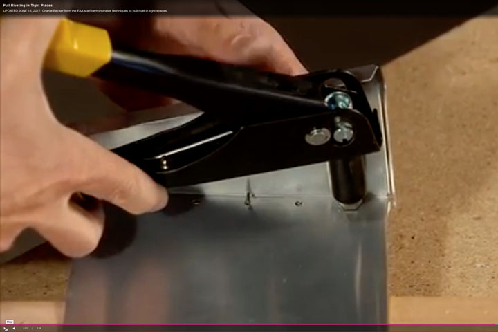


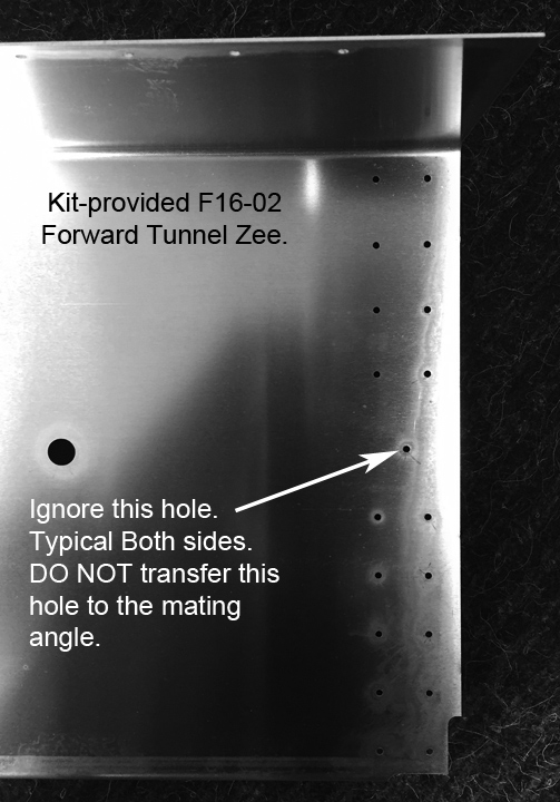
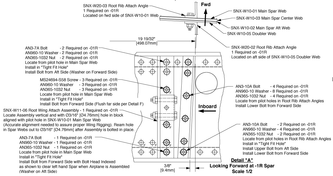
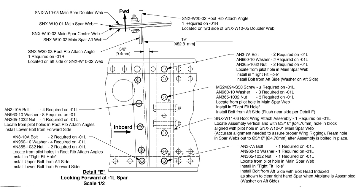
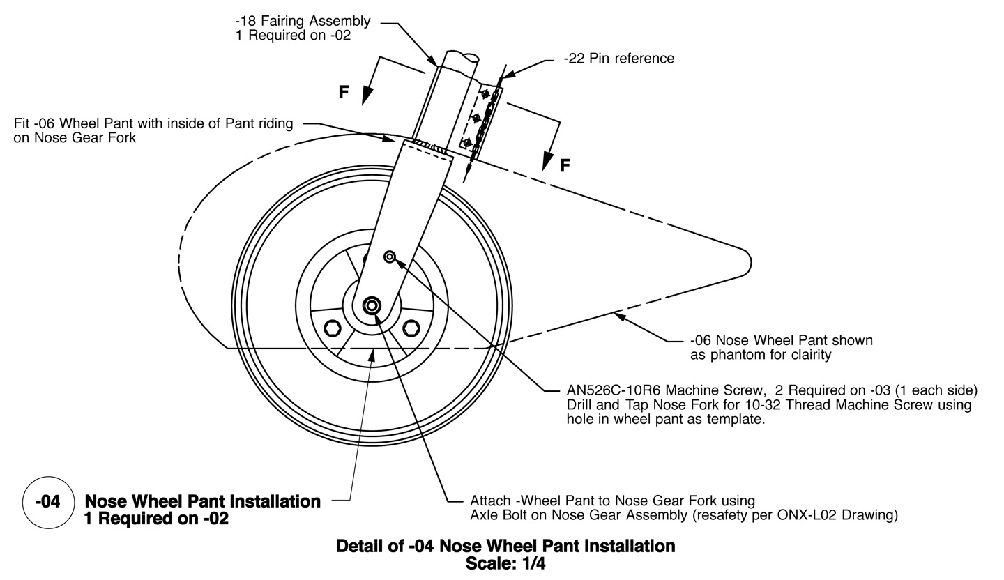
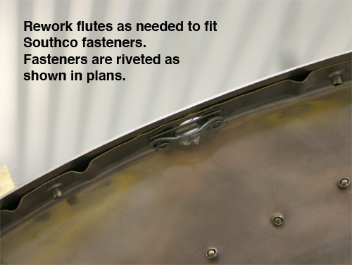
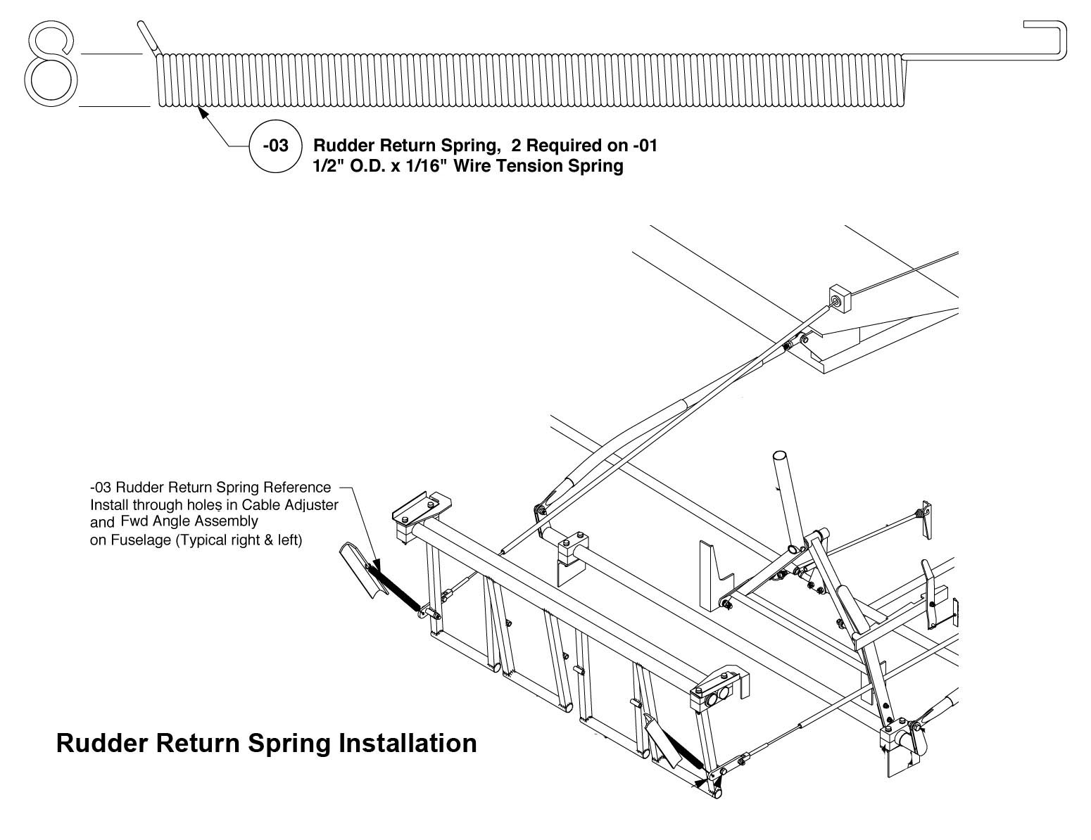
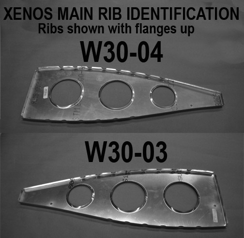
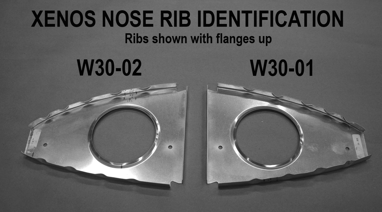
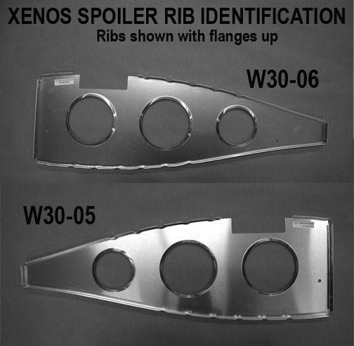