All Service Bulletins on Sonex Products are posted to this web site immediately, and distributed to our Tech Updates Mailing List.
Reporting Errors:
Please Contact Sonex Aircraft immediately to notify us of any suspected errors.
Service Bulletin Product Categories:
Tech Updates Mailing List |
|---|
|
Subscribe to the Sonex Aircraft Technical Updates Mailing List below (part of the Sonex and AeroConversions Web Updates mailing list) for automatic email notification of new drawing revisions, service bulletins and other technical documentation. |
General - All Airframe Models
| Service Bulletins: All/Multiple Airframe Models | |||
|---|---|---|---|
| Status | Models and Serial Numbers | Date of Issue | Reference Number |
| OPTIONAL | All B-Model Taildragger Airframes (Sonex-B, Waiex-B, and Xenos-B) | 12.10.25 | SNX-SB-015 |
|
Description: Corrective Actions: B-Model Engine Mount Production Revision and Plans Drawing Revisions: As-of the date of this revision, all new B-Model Standard Gear engine mounts will be produced with larger drill bushings to allow for use of AN5-30A bolts. Page L01 of Sonex-B, Waiex-B, and Xenos-B plans have been revised to change AN4 gear attach hardware to AN5. Aftermarket Components Advisory: Customers are advised to ensure a tight fit of titanium landing gear legs with any aftermarket or custom engine mounts or axles. If a loose fit exists, the engine mount or axle's gear leg receptacle must be sleeved by shim stock around the entire gear leg circumference to create a tight fit. |
|||
| Status | Models and Serial Numbers | Date of Issue | Reference Number |
| REQUIRED | General Workmanship Advisory for All Builders; Sonex-B, Waiex-B, Xenos-B, and Waiex (A-Model) Parts Shipped Between 04.26.23 and 04.26.24 | 05.13.24 | SNX-SB-014 |
|
Description: Parts Affected:
Corrective Action: General Advisories for All Builders: Grain Direction: |
|||
| Status | Models and Serial Numbers | Date of Issue | Reference Number |
| OPTIONAL | Aircraft Equipped with Rotax Engine Mounts | 10.04.22 | SNX-SB-013 |
|
Description: Corrective Action: Installation of this additional 1/2” brace tube is optional for customers seeking to minimize engine movement inside the cowling during start-up or shut-down of their Rotax engine. Original Sonex/Rotax engine mount purchasers may receive an 18" length of 1/2” OD x .035” Wall 4130 Steel Tube at no-charge via the Sonex Web Store, which can be cut to-fit and welded to your motor mount after removing the engine. The tube must be welded in place using accepted aircraft welding and repair practices. Optionally, registered Sonex aircraft owners may Contact Sonex Aircraft Tech Support and request an RMA to return their motor mounts for modification at reduced cost. Be sure to reference SNX-SB-013 in your message to Sonex Technical Support. |
|||
| Status | Models and Serial Numbers | Date of Issue | Reference Number |
| OPTIONAL | Aircraft equipped with ACV-P54-Kit Rotax Engine Mount Attach Kit | 10.04.22 Updated 08.29.23 |
SNX-SB-012 |
|
Description: Corrective Action: Original Purchasers of the ACV-P54-Kit Rotax Engine Mount Attach Kit experiencing this issue may receive an SNX-SB-012 Washer Update package at no-charge via the Sonex Web Store. Non-original owners of the ACV-P54-Kit Rotax Engine Mount Attach Kit may order these washers via the ACV-P54-Kit Service Parts category of the Sonex Web Store, or they may source/modify their own washers if desired. Updated 08.29.23: |
|||
| Status | Models and Serial Numbers | Date of Issue | Reference Number |
| REQUIRED | All Legacy Sonex, Waiex and Xenos Airframes | 05.31.22 | SNX-SB-011 |
|
Unsafe Center-mounted Throttle Installations: The cockpit MUST be configured so one of the pilot’s hands can remain on the stick at all times while the other hand remains free to operate the other controls (throttle, mixture, flaps, brakes, trim). Corrective Actions: If a center-mounted throttle is not necessary, the throttle (as well as mixture control and trim control) MUST be moved to the left side of the cockpit, near the flap and brake handles. |
|||
| Status | Models and Serial Numbers | Date of Issue | Reference Number |
| REQUIRED | All B-Model Airframes Supplied With One-Piece Fuel Tank Straps (SNB-G01-10) and SNB-G02-01 fuel tanks shipped prior to 09.08.22 | 06.25.21 Updated 11.11.21 Updated 10.05.22 |
SNX-SB-010 |
|
Description: Cause: What was Updated on 10/02/2022?
What was Updated on 11/11/2021? The revised procedure, detailed on Drawing SNB/WXB/XNB-G01 Rev D has the unseasoned tank installed, but loosely supported by the SNB-G01-11 two-piece fuel tank straps until the tank has been exposed to fuel for a period greater than 4 weeks. Then the straps can be snugged, but not tightened. Slight fore and aft movement of the straps at the bottom of the tank should be possible -- the straps should not be tightened so much that they cannot move at all. If your fuel tank has been installed and exposed to fuel, inspect the tank for deformation and provide photos and your aircraft's serial number to Sonex Aircraft Technical Support (tech@sonexaircraft.com). In all cases we have seen, distorted tanks remain temporarily airworthy as long as fuel level is maintained so the fuel level supply port is covered by fuel in all flight attitudes. Corrective Action: Un-Fueled Tanks, both Installed and Uninstalled Recently Seasoned Tanks Recently Fueled Tanks that are Installed but Not Distorted Previously Fueled Tanks Which are Distorted |
|||
| Status | Models and Serial Numbers | Date of Issue | Reference Number |
| OPTIONAL | Aircraft equipped with SNB-P53-01 Rotax Mount Bars | 05.05.21 | SNX-SB-009 |
|
Description: Corrective Action: Original purchasers of SNB-P53-01 Rotax Mount Bars interested in upgrading to the new AeroConversions Rotax Mount System may do so at no-charge via the Sonex Web Store Customers are asked to return SNB-P53-01 Rotax Mount Bars and any unused ACV-P01-19 Rubber Shock Mounts to: Sonex, LLC |
|||
| Status | Models and Serial Numbers | Date of Issue | Reference Number |
| OPTIONAL | All tailwheel-configured airframes fitted with a Machined Tailwheel Assembly (SNX-L03-20/-21 or SNX-L03-30/-31) | 09.13.18 | SNX-SB-008 |
|
Description: The risk of a failure increases if differential brakes are installed. The Sonex Aircraft Machined Tailwheel Assembly is not intended for use with differential brakes. Corrective Action: Units that have already been delivered can be refitted with the new hardware:
The hardware can be sourced from numerous aircraft hardware supply sources or ordered through the Sonex Aircraft Webstore, at: https://www.sonexaircraft.com/eshop/cart.php?target=product&product_id=17717&category_id=397 Ongoing inspection: |
|||
| Status | Models and Serial Numbers | Date of Issue | Reference Number |
| REQUIRED | Jabiru 3300 Tri-Gear Configurations (This includes all aircraft fitted with motor mount part numbers SNX-P22-02 or SNX-P22-08. | 08.24.11 | SNX-SB-007 |
|
Description: This area must also be inspected immediately if nose wheel vibration is detected, a hard landing is experienced, after rough field operation, or if the nose strut is stressed sideways from improper ground handling. Any crack found must be repaired prior to your next flight. Optional Corrective Action: Registered Sonex aircraft owners can Contact Sonex Aircraft Tech Support and request a free tube, part number SNX-P22-07, which can be welded to your motor mount after removing the engine. The tube must be welded in place using accepted aircraft welding and repair practices. Ongoing Inspection: See diagram with full service bulletin text in download: Jabiru 3300 Tri Gear Motor Mount Tube Installation instruction sheet: |
|||
| Status | Models and Serial Numbers | Date of Issue | Reference Number |
| REQUIRED | All Sonex, Waiex and Xenos Aircraft. | 06.28.11 | SNX-SB-006 |
|
Description: Mandatory Inspection: Mandatory Corrective Action: Main Gear Installation: Tail Wheel Installation: Install the castle nut by tightening it until it is snug and then loosen the castle nut 1/4 to 1/2 turn before installing the cotter pin. Do not over-tighten the castle nuts on installation. Proper bolt sizes can be found in the “L” section of the aircraft blueprints. Example: Sonex drawing SNX-L01, Detail A, AN4C-17 bolts and AN365-428 nuts to be replaced by AN4-17 bolts, AN310-4 Castle nuts, and MS MS24665-208 cotter pin. Ongoing Inspection: Download Printable PDF File: |
|||
| Status | Models and Serial Numbers | Date of Issue | Reference Number |
| REQUIRED | All Sonex, Waiex and Xenos Aircraft. | 11.02.09 | SNX-SB-005 |
|
Description: All motor mounts shipped from Sonex since June of 2005 have this heavier-wall tubing already installed on the motor mount. These are identified on packing lists and labeled with -08 part numbers. In over 11 years of service (and currently 279 completions), Sonex Aircraft has received a total of 4 reports of motor mount support tubes breaking between the lower motor mount pin and the welded area that picks up the cross-tubes. 2 of these reports were on 3300 Jabiru Engine Std Gear Mounts and 2 of these reports were on 2200 Jabiru Engine Std Gear Mounts. In all 4 cases, these were found during inspections and were obvious with a visual inspection. All Sonex, Waiex, and Xenos Aircraft that do not have -08 motor mounts installed shall visually inspect the area of the motor mount pins for cracks prior to next flight and at regular intervals not to exceed 25 hours of flight time. If area shows signs of cracks the aircraft shall be taken out of service until suitable repairs have been made. (update 12.04.09) Alternatively, customers may purchase and install a new -08 motor mount, or make the following upgrade/repair to their existing mount: SNX-Mount-Repair.pdf |
|||
| Status | Models and Serial Numbers | Date of Issue | Reference Number |
| REQUIRED | All Sonex and Waiex Tri-Gear Aircraft purchased before May 1st, 2007 | 07.03.07 | SNX-SB-004 |
|
SNX-C02-10 NOSEWHEEL PUSH ROD SPRING CHECK: A correct Nosewheel Push Rod Spring Installation looks like this: An incorrect Nosewheel Push Rod Spring Installation looks like this: If your Sonex Supplied SNX-C02-10 Springs are not installed yet, you may measure the inside diameter to determine if they are correct or not. The correct springs measure over 0.60" on the inside diameter: The incorrect springs measure under 0.60" on the inside diameter: If you determine that you do not have the correct SNX-C02-10, please Contact Sonex Aircraft Technical Support. An RMA Number will then be issued for the return and inspection of the incorrect parts. If found to be the incorrect parts, replacements will be sent to you at no charge.
|
|||
| Status | Models and Serial Numbers | Date of Issue | Reference Number |
| REQUIRED |
All Flying Sonex Aircraft |
8.22.05 |
SNX-SB-002 |
|
CHECK ALL WELDED COMPONENTS FOR CRACKS IMMEDIATELY: Note: A crack in your black powder-coated welded component will show as a bright white/gray line and any separation of the structure will be visible to the naked eye. A flashlight and magnifying glass should be used to assist in the inspection. Any crack found must be repaired prior to your next flight. |
|||
Sonex
| Service Bulletins: Sonex Airframes | |||
|---|---|---|---|
| Status | Models and Serial Numbers | Date of Issue | Reference Number |
| OPTIONAL | All Sonex Aircraft | 11.21.05 | SNX-SB-003 |
|
UPGRADE OF SNX-F10-03 ANGLE: Note: This service bulletin does not apply to the Waiex or Xenos. |
|||
| Status | Models and Serial Numbers | Date of Issue | Reference Number |
| REQUIRED | All Flying Sonex Aircraft | 8.22.05 | SNX-SB-002 |
|
CHECK ALL WELDED COMPONENTS FOR CRACKS IMMEDIATELY: Note: A crack in your black powder-coated welded component will show as a bright white/gray line and any separation of the structure will be visible to the naked eye. A flashlight and magnifying glass should be used to assist in the inspection. Any crack found must be repaired prior to your next flight. |
|||
| Status | Models and Serial Numbers | Date of Issue | Reference Number |
| REQUIRED | All Sonex Aircraft with SNX-C02-01 Rudder Pedal Assemblies | 6.07.02 | SNX-SB-001 (3 pages) |
|
Sonex Rudder Pedal Service Check and Upgrade or Replacment: |
|||
Waiex
| Service Bulletins: Waiex Airframes | ||||
|---|---|---|---|---|
| Status | Models and Serial Numbers | Date of Issue | Reference Number | |
| REQUIRED | All Waiex, Waiex-B, Xenos, and Xenos-B Aircraft | 04.29.20 | WIX-SB-003 | |
|
Description:
Inspection: Corrective Action:
Ongoing Inspection: |
||||
| Status | Models and Serial Numbers | Date of Issue | Reference Number | |
| REQUIRED | All Waiex Aircraft | 08.21.14 | WIX-SB-002 | |
|
Description: Download: WIX-C04-01-FwdRudderCable.pdf Download: WIX-C04-03-AftRudderCable.pdf Image of correct Nicopress Sleeve and Thimble Installation - Download: WIX-SB-002-Cable_Swage_Inspection.pdf Note that a cable installed flush with the end of the Nicopress Sleeve is serviceable and does not present a safety hazard. Mandatory Inspection: Required Corrective Action:
Note: Flying aircraft will be given shipping priority. |
||||
| Status | Models and Serial Numbers | Date of Issue | Reference Number | |
| REQUIRED | All Waiex Aircraft (Sonex Airframe Model NOT included in this Service Notice) | 11.15.11 | WIX-SB-001 | |
|
This Mandatory Service Notice details the addition of 3 aluminum structural components to the Waiex Tail/Fuselage attachment. History: Warning: Service Parts: |
||||
Waiex-B
| Service Bulletins: Waiex-B Airframes | |||
|---|---|---|---|
| Status | Models and Serial Numbers | Date of Issue | Reference Number |
| REQUIRED | All Waiex-B Aircraft Equipped with SNB-C05-10 Feedback Linear Actuators (10 13/16" Retracted Length, Hole-to-Hole) | 12.20.22 | WXB-SB-001 |
|
Description: Disposition:
Corrective Action:
|
|||
Xenos
| Service Bulletins: Xenos Airframes | ||||
|---|---|---|---|---|
| Status | Models and Serial Numbers | Date of Issue | Reference Number | |
| REQUIRED | All Waiex, Waiex-B, Xenos, and Xenos-B Aircraft | 04.29.20 | XNS-SB-003 | |
|
Description:
Inspection: Corrective Action:
Ongoing Inspection: |
||||
| Status | Models and Serial Numbers | Date of Issue | Reference Number | |
| REQUIRED | All Xenos Aircraft | 08.21.14 | XNS-SB-002 | |
|
Description: Download: XNS-C04-02-FwdRudderCable.pdf Download: XNS-C04-07-AftRudderCable.pdf Image of correct Nicopress Sleeve and Thimble Installation - Download: XNS-SB-002-Cable_Swage_Inspection.pdf Note that a cable installed flush with the end of the Nicopress Sleeve is serviceable and does not present a safety hazard. Mandatory Inspection: Required Corrective Action:
Note: Flying aircraft will be given shipping priority. |
||||
| Status | Models and Serial Numbers | Date of Issue | Reference Number | |
| REQUIRED | All Xenos Aircraft (Sonex Airframe Model NOT included in this Service Notice) | 11.15.11 | XNS-SB-001 | |
|
This Mandatory Service Notice details the addition of 1 aluminum structural component to the Xenos Tail/Fuselage attachment. History: Warning: Service Parts: |
||||
SubSonex
| Service Bulletins: SubSonex Airframes | |||
|---|---|---|---|
| Status | Models and Serial Numbers | Date of Issue | Reference Number |
| REQUIRED | Ruddervator Counterweight Inspection and Securement | 09.15.25 | JSX-SB-010 |
|
Mandatory Inspection: Sonex has received one customer report of loose counterweights in factory-supplied JSX-T06-02 Ruddervator Tip assemblies. All SubSonex customers must inspect their ruddervator counterweight tip assemblies for loose counterweights, which can be easily moved inside the cavity when loose due to an inadequate epoxy bond between the lead counterweight and aluminum ruddervator tip cavity. This inspection must be conducted before the aircraft's next flight.
Corrective Action: If lead counterweights are found to be loose upon inspection, the following repair must be completed before the aircraft's next flight. If lead counterweights are not loose, the following steps may be executed as a precaution, if desired.
This inspection and any corrective action taken must be documented in your airframe’s logbook before the aircraft's next flight. |
|||
| Status | Models and Serial Numbers | Date of Issue | Reference Number |
| REQUIRED | PBS TJ100 Engines (affected engine serial numbers specified in attachment) | 12.16.24 | B24311163 |
|
PBS has issued Service Bulletin B24311163 for the recall of PBS engines for a mandatory turbine inspection (attached). This affects PBS TJ100 E3S, TJ100 E3B and TJ100B engine models. The serial numbers affected are listed in the service bulletin. Please do not fly your aircraft until after this turbine inspection has been completed. PBS will cover the cost of the shipping and the cost to complete this service bulletin. Affected customers will be notified when to send your engine. A commercial invoice and FedEx shipping label will be issued to you by PBS for the shipment of your engine. Download: B24311163_TJ100_Turbine_blades_inspection.pdf Also attached is a letter from PBS factory concerning the TBO limits and how PBS is handling engines that exceed any of these limits. Download: 021-PR-TBO_TJ100.pdf This service bulletin supersedes Sonex service bulletin JSX-SB-009 Please contact PBS Aerospace with any questions about this service bulletin. |
|||
| Status | Models and Serial Numbers | Date of Issue | Reference Number |
| REQUIRED | PBS TJ100E3S Engines Serial Number 1446 and Earlier | 11.26.24 | JSX-SB-009 |
|
DO NOT FLY ENGINE: Pending New PBS Service Bulletin Sonex LLC has been notified of a pending PBS Service Bulletin requiring the return of some or all engines to the PBS factory for inspection and possible replacement of the turbine blade. This new service bulletin is set to be published by PBS by November 29th 2024 and affects all PBS TJ100E3S engines up-to and including serial number 1446, along with TJ100B and TJ100E3B engines. Sonex is requiring that all SubSonex aircraft be grounded until completion of the new service bulletin procedures to be published by PBS. This service bulletin will extend and/or supersede PBS service bulletin B19311066 Revision 1 by requiring mandatory inspection of engines by PBS before being returned to service. More details will be forthcoming after publication of the pending service bulletin. |
|||
| Status | Models and Serial Numbers | Date of Issue | Reference Number |
| REQUIRED | PBS TJ100 Engines (affected engine serial numbers specified in attachment) | 09.30.24 | B19311066 Revision 1 |
|
PBS TJ100 Idle Speed Change and Turbine Wheel & Nozzle Wheel Inspection - Mandatory Service Bulletin (Supersedes 12/19/2019 Service Bulletin) PBS has issued the following MANDATORY SERVICE BULLETIN requiring more frequent inspection of turbine blades via endoscope, and changing the minimum idle speed of the engine from 34,000 RPM to 37,000 RPM. Borescope inspections can be conducted by the aircraft owner and should be conducted every 25 operating hours or every 30 starts. Pilots are instructed to not use minimal engine speed on the ground. Engines must be run at a minimum of 64 percent RPM. Engine serial numbers affected are listed in the service bulletin. Download: PBS_TJ100E3S_Service_Bulletin_B19311066_rev_1.pdf Inspection Procedure Inspection Procedure is detailed in the PBS TJ100 engine manual (section 6.8 for TJ100E3S). Manual excerpt detailing procedure available here: Download: TJ100E3S_PP-22E3S_borescope_inspection_excerpt.pdf This inspection must be documented in your engine’s logbook at each inspection. Sonex has updated the SubSonex Inspection Program fillable PDF in-accordance with this revised PBS service bulletin. Download: Inspection_Program_Template-Fillable_SubSonex_JSX-2_RevB_101024.pdf |
|||
| Status | Models and Serial Numbers | Date of Issue | Reference Number |
| AS-REQUIRED | SUBSONEX Aiframes up-to SN: JSX0044 | 07.22.21 | JSX-SB-008 |
|
Elevator Travel Limited by Elevator Stop Bracket Description: Corrective Action:
|
|||
| Status | Models and Serial Numbers | Date of Issue | Reference Number |
| REQUIRED | ALL SUBSONEX Airframes | 01.20.21 | JSX-SB-007 |
|
SubSonex Fuel Filter Cleaning – Mandatory Service Bulletin Description: Corrective Action
If any debris is found in the primary fuel filter per the above inspections, the fuel pump filters (Drawing JSX-G03, Detail D) and PBS Supplied engine fuel filter, part number 170190.05 or equivalent (Drawing JSX-G03, Detail E) must be inspected and cleaned. Loss of Fuel Pressure: Download:
Updated SubSonex Inspection Program: If not already conducted during the most-recent applicable benchmark listed above, this inspection/service must be completed before your next flight and documented in your aircraft’s logbook. |
Status | Models and Serial Numbers | Date of Issue | Reference Number |
| REQUIRED | ALL SUBSONEX Airframes | 05.30.19 | JSX-SB-006 |
|
Rudder Cable Bushings – Mandatory Service Bulletin It has come to the attention of Sonex Aircraft that some SubSonex builders have not installed bushings in locations where rudder cables pass-through the airframe structure. While not specifically called-out in SubSonex plans, protection of control cables passing-through metal aircraft structure is standard building practice. Corrective Action All SubSonex airframes must be checked to ensure that bushings are installed at all control cable pass-through locations in the airframe. Bushings must be installed if they are not present. The following drawing identifies bushing locations. Download: JSX-SB-006.pdf This inspection/service must be completed before your next flight and documented in your airframe’s logbook. |
Status | Models and Serial Numbers | Date of Issue | Reference Number |
| REQUIRED | ALL SUBSONEX Airframes | 05.02.19 | JSX-SB-005A |
|
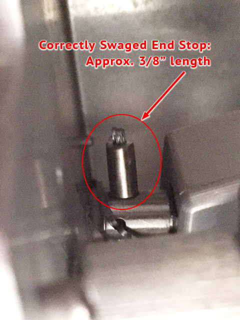
JSX-C02-10 Forward Rudder Cable Assembly – Mandatory Service Bulletin Sonex has identified a problem with the swaging of the cylindrical terminal end of the JSX-C02-10 Forward Rudder Cable Assembly in some kits. The rudder cable may pull-out of the cylindrical terminal, causing loss of nosewheel steering. Revision A: Many kits have correct swaging. See updated Corrective Action below. Corrective Action (Updated) Send a picture of JSX-C02-10 stainless steel stop sleeve to Sonex Aircraft Product Support via the Sonex Contact Form for verification of correct swaging technique. Access through the nose gear door, reference plans page JSX-L02, Detail B to visually identify. Swaged end stop should be smooth and approximately 3/8" in length per the following image. Download: JSX-SB-005A.jpg If the end stop is 5/16" in length, has any visible grooves, or beveled ends, it must be removed from your aircraft and sent back to Sonex Aircraft for repair. This inspection/service must be completed before your next flight and documented in your airframe’s logbook. |
|||
| Status | Models and Serial Numbers | Date of Issue | Reference Number |
| REQUIRED | SUBSONEX (Serial Number JSX003 to and including JSX0016, JSX0018, JSX0020) | 09.26.18 | JSX-SB-004 |
|
Aileron Counter Balance Rear Spar Cut-out Position Some outboard wing panels were delivered with an incorrectly positioned cut-out for the aileron counterbalance assembly. The presence of the error will be obvious to anyone fitting their ailerons. The attached drawing shows the proper cut-out for any impacted airframes. |
Status | Models and Serial Numbers | Date of Issue | Reference Number |
| RECOMMENDED | ALL SUBSONEX Airframes | 05.22.18 | JSX-SB-003 |
|
Nose Wheel Retaining Hardware Change Drawing JSX-L02 (Rev G and above) implements changes to the hardware that retains the nose wheel. Although no problems have occurred to-date, these changes improve the retention of the nose wheel assembly. It is recommended all owners implement these changes. Download: JSX-L02_RevG_Mark-up.jpg |
|||
| Status | Models and Serial Numbers | Date of Issue | Reference Number |
| REQUIRED | SUBSONEX (Serial Number JSX0003 to and including JSX0012) | 06.13.17 | JSX-SB-002 |
|
Nose Wheel Fork Set Screw Installation – Mandatory Inspection Drawing JSX-L02 (Rev D and prior) depicts a set screw (callout number 5, part number JSX-L02-42) that MUST engage the hole in the Clevis Pin (callout 42, part number AN394-53). Further, the set screw must be Locktited in place. Failure of the set screw to engage the clevis pin can result in separation of the nose fork assembly. Drawing JSX-L02 has been revised (Rev E and above) to more clearly illustrate the installation of the set screw. A JPEG of the revision can be viewed here: If your SubSonex is licensed, this modification must be completed before your next flight and documented in your airframe’s logbook. |
|||
| Status | Models and Serial Numbers | Date of Issue | Reference Number |
| REQUIRED | All SUBSONEX Airframes Delivered Prior to June 13, 2017 (s/n JSX0003 to and including s/n JSX0012). | 06.13.17 | JSX-SB-001 |
|
Control System Collar Roll Pin Installation – Mandatory Service Bulletin Sonex Aircraft have identified the need to pin the control pushrod collars to the pushrod (JSX-C03-02). Failure to do so can result in the collars moving on the pushrod if the bolts come loose, resulting in loss of positive control of the control surfaces. The linked drawing shows the modification and identifies the size of the roll pin used. A copy of this drawing and two roll pins have been mailed to each affected airframe. |
|||
AeroConversions Service Bulletins
Service Bulletins for all AeroConversions products can be found at the following pages on the AeroConversions web site:

