
A lot has happened since our last update on the construction of the new Sonex Highwing prototype, and on Friday, June 6th, we ran the engine for the first time! The list of tasks required to complete the aircraft is getting very short, and we’re almost ready for final inspection and first flight. We are awaiting the aircraft registration to come-back from the FAA and have an inspector lined-up with the goal of achieving first flight before EAA AirVenture Oshkosh 2025. Be sure to subscribe to our mailing list for our next exciting update announcing the Highwing’s first flight!
Engine Start
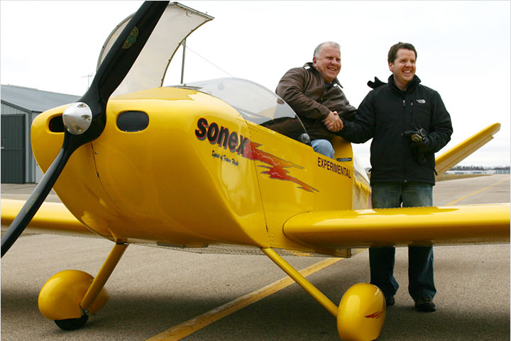
As reported above, we started the 130 horsepower UL Power UL350iS engine on the Sonex Highwing for the first time on Friday. The engine fired right-up and ran great with no issues whatsoever. We even took a short taxi test and did some brake checks, all with nominal results.

Completed Since Our Last Update:
|
Deposits are refundable less a $50 Cancellation Fee. |
Get yourself in line for a kit by placing a $500 Kit Reservation Deposit today. These deposits not-only get you a place in line amongst your fellow future Highwing builders, but also helps Sonex to plan for kit inventory needs. Kit Reservation Deposit Holders will be given the opportunity to turn their reservations into firm orders following the first flight tests of the prototype aircraft. Deposits are refundable minus a $50 cancellation fee. If you have any questions, please reach-out to us via our Contact Form.
Windshield and Doors
The windshield tooling shown in our February and April updates was completed and we quickly had success forming a good windshield with only a couple scrap pieces of plastic. The heated flat wrap forming process has proven to be relatively easy, and while the windshield installed in this prototype isn’t quite flawless, it’s very good and we look forward to perfecting the process in short-order.
Machined door hinges for the Highwing arrived recently to finish-off the doors. The hinges are a perfect fit and doors are on! Our original plan of racecar-type door release lanyard on the interior of the aircraft has been replaced with a compact, lightweight and inexpensive door handle, which allowed us to make the door release less of a “hair trigger” vs. the lanyard.
 A Sonex Highwing windshield on the forming buck after heating in our canopy oven.
 The first fit check of the Sonex Highwing windshield.
 CNC machined Sonex Highwing door hinges. Pins are inside for aerobatic door jettison and the hinges have integrated door-open stops.
 Doors installed. Interior door trim panels will be forthcoming.
Peeling off the protective plastic: so satisfying!
 The view through the windshield. Ignore the rogue cable bundle on the right, that will be attached to the A-pillar.
 Door installed and closed. We’re going to paint the aircraft, but we might just have to polish those slick door hinges to show them off.
 These compact, lightweight interior door handles are a perfect fit. Some of you might recognize them from a very popular car!
Wings and Control Surfaces
Final wing skinning and installation of the outboard wing panels was completed in mid-May, along with construction and installation of the ailerons and flaps. In-process now are simple metal flap root fairings that will allow preflight inspection of the flap actuation hardware when the flaps are down. We will make first flight with the aerobatic-span endplates installed, which are also in-process. We’ll be hot-wiring foam to fiberglass molding plugs for the full-span wing tips soon. As a reminder, the aircraft will have easily interchangeable wing tips: For aerobatics with 2 persons aboard simple aluminum end-plates cap-off the wings for a 23′ 1.3″ span, and small 18.55″ span fiberglass tips will be installed for the full 26′ 2.4″ span configuration.
 The Sonex Highwing’s first look at the sun with fully skinned inboard and outboard wings in mid-May.
 A great view of the finished wings with flaps and ailerons installed during last Friday’s engine run and taxi.
 A look at the wing center section with installed skylight windows. The flap connections to the flap torque tube can also be seen here.
 A closer look at the flap torque tube hardware linkage to the flap drive rib, accessible through a notched-out section of the upper flap skins.
 Simple, easily removeable metal flap root fairings will conceal the flap torque tube linkage hardware when the flaps are up.
 With flaps down, the flap torque tube linkage to the flap drive rib can be easily inspected during preflight.
Aileron and Elevator Controls
The CNC machined lower aileron torque tube bellcrank arrived with the door hinges, allowing us to tie our unique control stick frame together with the torque tube and elevator pushrod in the center armrest tunnel. The video at-right shows the first fit check of the installed system and we’re happy to report that it’s working exceptionally well and the controls are nice and smooth.
This system allows us to retain pushrod controls for aileron and elevator, and have the easily interchangeable dual-stick, vs. pilot-side only stick, vs. cabin center-stick configurations featured in the Sonex Highwing. Pushrod aileron and elevator controls are important for responsive, aerobatic handling and high-speed flight with greatly reduced risk of flutter.
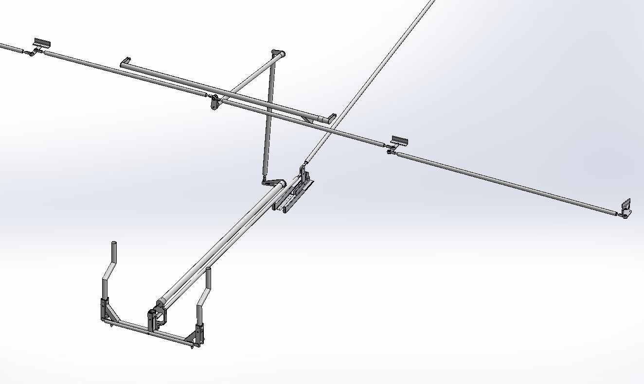 Sonex Highwing flight control system layout.
Headset Jacks and Control Stick Wiring
Headset jacks have been installed in the center fuselage tunnel in front of seats. Since the space inside the 2″ wide tunnel is a little tight, we made simple 3D printed insulating caps to make sure the typically exposed headset jacks remained isolated from each other and any possible debris. The caps made for a clean installation that worked great!
We’ve also completed wiring to the control stick frame and the pilot’s control stick for electric trim and push-to-talk. The left and center stick frame receptables have Molex connectors for elevator trim (using our AeroConversions Trim System spring-loaded trim installation with a linear actuator instead of the AeroConversions trim knob), while the right-hand stick frame receptable has a Molex connector for PTT only. Builders can install trim and electric flaps control for both seats if an electronic controller is employed to resolve conflicting inputs (one pilot commanding trim or flaps down at the same time that the other pilot is commanding trim or flaps up), which we did not install in this prototype.
 Pilot and co-pilot headset jacks are installed on either side of the center tunnel. Our 3D printed insulation caps did a nice job of isolating the jacks from each other in this rather tight space.
 Another view of the installed headset jacks from the co-pilot side with insulating caps seen inside the fuselage tunnel.
 Control stick frame all wired up for elevator trim and PTT.
 Wired-up control stick frame and stick receptacles with controls cover in-place.
 AeroConversions control stick grip assembly with trim and PTT switches in-place.
 Finished pilot’s stick assembly installed in the center control stick receptacle.
Throttle Quadrant
A throttle quadrant has been installed on the pilot’s side with increased cable travel for the UL Power engine. We will fly with a left-hand throttle quadrant only for first flight, while we continue to develop our dual throttle installation concepts for this new quadrant design, with the goal of integrating the co-pilot side throttle with no slop in the system. We will be testing and evaluating various cable splitter and other designs for a dual throttle during the flight test program.
 Pilot’s side throttle quadrant installed.
Brakes
As evident from the video at the top of this page, the brakes are installed and working great. The design of the brake pedals had to be revised to increase their strength. We will make first flight with pilot’s side brakes only, and will experiment with the co-pilot’s side brake installation as-shown in our February update during the flight test program.
 Pilot’s side brakes installed and working great!
Fuel System
The Fuel system is completed for inspection and first flight, although we don’t have our wing tanks from our supplier yet. First flight will likely be made without the wing tanks installed. All plumbing to the wing tanks is complete, however, along the main tank vent line to the wings.
 Pilot’s side wing tank valve and main tank vent line installed (over pilot’s side door).
Cowling
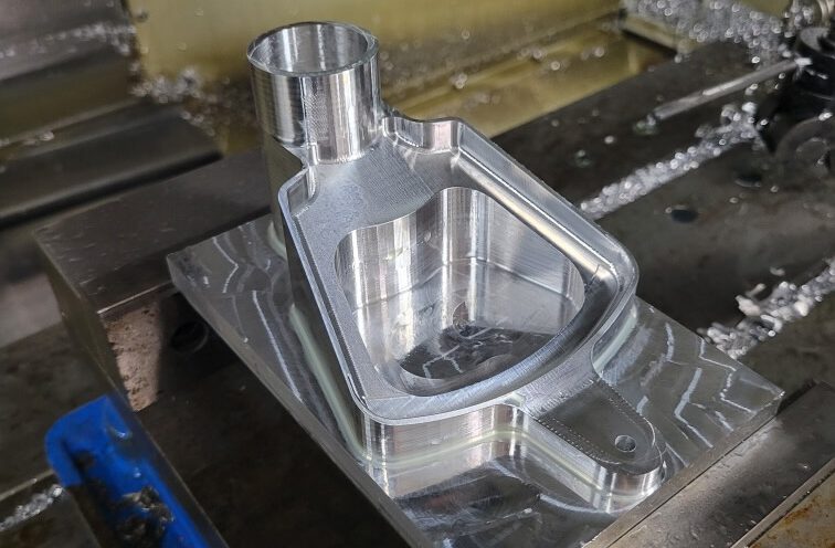
Cowling installation is in-process as we speak. We are using the standard B-Model cowling, however, UL Power engine installation requires an inlet for the oil cooler, which extends past the draft lines of the existing cowling slightly. We are glassing-up an oil cooler scoop that we plan to offer as a graft-on piece for future Sonex/UL Power builders.
 UL Power oil cooler inlet, glassed over sculpted modeling clay applied to the existing cowl.
Seat Back Supports
Supports for the adjustable folding seat backs have been installed, allowing three different seat back angles combined with the two available seat back hinge points shown in our previous updates to offer a large amount of flexibility in fitting pilots of different sizes comfortably in the aircraft.

|
|
Sonex Highwing Estimated SpecificationsSubject to change without notice
* Sonex Highwing features easily interchangeable wing tips for different span configurations. Sonex Highwing is designed to take advantage of the new FAA MOSAIC rules for Light Sport Aircraft! Specifications & Performance Subject to Change Without Notice. |
||||||||||||||||||||||||||||||||||||||||||||||||||||||||||||||||||||||||||||||||||||||||||||||||
Sonex Aircraft Models
- Sonex Highwing
- Sonex-B
- Waiex-B
- Xenos-B Motorglider
- Onex
- SubSonex Personal Jet
- Sonerai Sport Aircraft

