In recent weeks Sonex Aircraft has made great progress on a new liquid cooling system for the AeroVee Turbo. The purpose of this system is to reliably reduce temperatures of the turbocharger bearing block to reduce the chances of oil coking and turbo seizing.
History:
Around mid-year 2016 Sonex Aircraft began receiving reports of turbo seizing in AeroVee Turbo systems in the field. Around this time, Sonex Aircraft also experienced a seized turbo on “Red One,” the Waiex B-Model prototype. Through investigations over the following months, four distinct and separate causal factors were identified. These factors were seen in varying degrees in the seized factory turbocharger, and in turbos received from customers for service:
- Oil Coking due to excessive turbocharger heat and stagnation of oil in the turbocharger bearing block & oil drain fitting after engine shut-down.
- Excessive wear of bearings and turbine shaft bearing surfaces due to particulates found in newly-built engines. Original AeroVee Turbo engine prototypes were converted from engines that had already passed their break-in period.
- Possibility of turbo housing rust particulates. This is a documented issue with low-time (under 100 hrs.) turbochargers in certified aircraft turbocharging systems. The low-time turbo is not yet “seasoned” and surface rust can form, seizing the turbocharger.
- Recent industry advisories about the incompatibility of 100LL and full-synthetic oil. Full-synthetic oil does not keep lead in-suspension and therefore can cause lead deposits in the oil system, which could contribute to turbo coking. Note that this variable can be eliminated if running auto fuel and full-synthetic oils, which will withstand the high turbo temperatures better.
Modification and Testing:
The AeroVee Turbo installation in “Red One” was modified to add an external spin-on oil filter as an additional layer of filtration to the existing “mini sump” filter in the AeroVee Turbo engine sump. The spin-on filter is located directly upstream of the turbocharger oil inlet. Additionally, a new AeroVee Turbo drain sump was added to the system to reduce stagnation of oil in the bearing block and turbo drain fitting after engine shut-down.
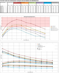
The turbocharger insulation blanket was removed from the system, and five progressive modifications to a stainless steel heat shield were tested to bring-down turbocharger bearing block temperatures (see AeroVee_Turbo_Air_Cooled_Test_Data_Summary.pdf ), allowing heat to escape from the turbocharger during the post-shutdown “heat soak” time frame. Turbine housing temperature (measuring heat soak of the cast turbine housing), bearing block temperature, and ambient cowling temperature directly above the turbocharger at the upper engine mounts were monitored. The final iteration of the shroud can be seen as the gray line in the test data tables, with the average peak temperature of 270 degrees F. This represents a reduction of approx. 60 degrees F. from the original system configuration, bringing max temps below 280 degrees, which was considered by Sonex Aircraft to be a critical threshold for oil coking. It can be seen that maximum heat soaking of the bearing block occurs approximately 15 minutes after engine shut-down.
Service Bulletin:
As a result of the tested modifications discussed above, AeroVee Turbo service bulletin ACV-SB-091616-1B was issued in Fall, 2016 ( http://www.aeroconversions.com/support/aerovee_sb.html ). The Service Bulletin included the items summarized here (read the full service bulletin online):
- Change to semi-synthetic oils if using 100LL fuel.
- Idle-power cooling run prior to engine shut-down.
- Verification of adequate manifold pressure during run-up and takeoff roll (abort takeoff if 40” MAP is not observed during takeoff roll).
- Re-clocking of turbocharger in tailwheel aircraft for better turbo oil drainage post-shutdown.
- Additional oil filter.
- Modification to original oil drain fitting, or replacement with new AeroVee Turbo drain sump.
- Replacement of turbo blanket with new stainless heat shield.
- Chemical flush maintenance procedure.
More Problems:
After issuance of the service bulletin linked above, turbocharger service issues continued to come-in from the field. Each customer was questioned about adherence to the service bulletin and additional measures per the service bulletin such as chemical flush were recommended by Sonex Aircraft. The problem of turbo sticking, or complete seizure persisted and the documented experience of certified aircraft turbochargers with regard to rust deposits appeared to be less of a factor than originally thought. Sonex Aircraft refocused its efforts on further heat reduction as a result.
The Case for Air Cooling:
Air cooling was a design goal of the AeroVee Turbo system from the beginning, as no dedicated turbocharger liquid cooling systems exist, that we have found (all rely upon engine coolant in liquid cooled engines). Air cooling allows for the lightest possible installation weight and greatest possible simplicity, as it does for the engine itself. Further, no data can be found regarding ideal turbocharger bearing block temperatures. Sonex Aircraft had to set it’s own limits based on “knowns” of oil exposure to other hot engine parts (cylinders, heads, etc.). While many have questioned the choice of a water-cooled turbo in an air cooled application, it was the advice of our turbo vendor that they see better heat dissipation with their turbo in an air cooled application than they do on many air-cooled turbo designs. We have no apples-to-apples data comparing our turbo to an air cooled turbo, however, and we found it best to move-on to development of a water-cooled system given the service difficulties.
Liquid Cooled System:
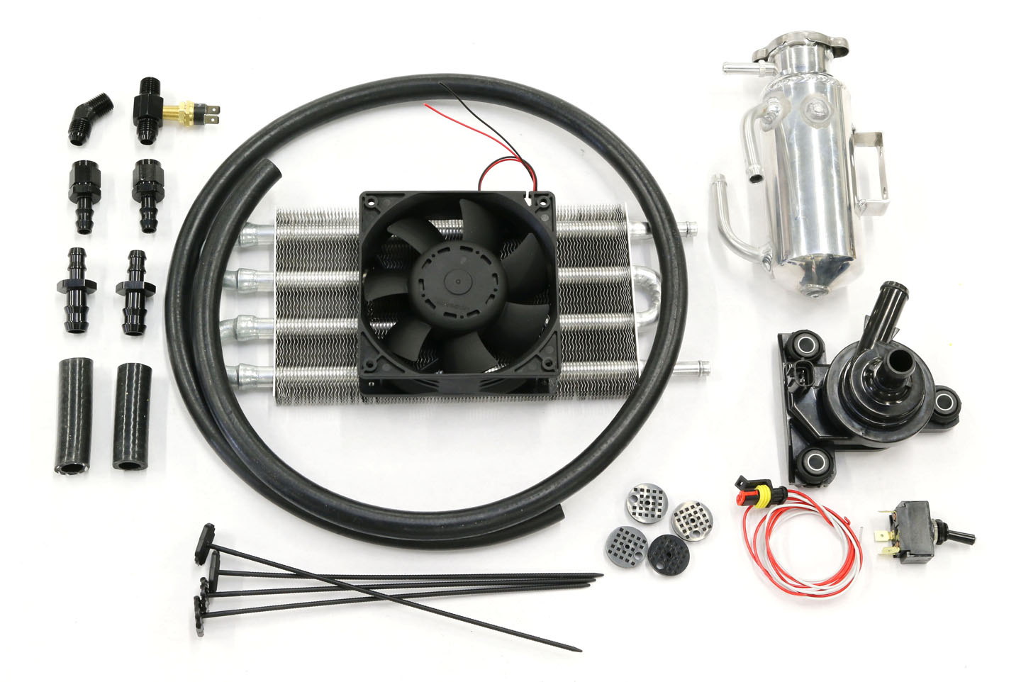
Sonex Aircraft has tested 3 basic variations of a simple, light weight liquid cooling system with very promising results thus-far (see AeroVee_Turbo_Cooling_System_2718.jpg, AeroVee_Turbo_Cooling_System_2721.jpg, AeroVee_Turbo_Cooling_System_2733.jpg and AeroVee_Turbo_Cooling_System_6255-20.jpg ). The basic system components and characteristics are as-follows:
- Small accumulator tank
- Radiator
- Electric fan
- Electric pump
- Total system weight with fluid: under 5 lbs.
- Uses waterless high-temp fluid
- Observed a 0.1 volt drop in battery charge when running the system for 35 minutes after engine shut-down. Current draw of the system is approx. 2.2 Amps.
The electric pump was added to the system after initial tests failed to provide adequate coolant circulation from convection alone. The pump is a popular automotive electronics cooling pump, and we found it to be very effective in reducing and stabilizing temperatures. Having the pump in the system and not relying on natural convection is valuable for tighter engine installations (Legacy “A-Model” aircraft or the Onex) allowing the radiator to be mounted pretty much anywhere.
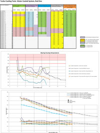
Testing results from the various iterations of the system can be seen on AeroVee_Turbo_Liquid_Cooling_Test_Data_Summary.pdf.
The “red line” for maximum bearing block temperature was lowered to 260 degrees F as the new goal for this system. Note that there is a lot of variability shown in this early test data, as many things were tested to measure immediate results, such as manually shutting-down the coolant pump or radiator fan and measuring cool-down cycles with the upper cowling cowling removed. The color-coded legend found at the right of the data table corresponds with the colors in the data table and shows where variables were introduced. The results of those variables can be easily seen in the data graph.
The latest version of the system (data set 5) has larger upper cowling vents (4″ diameter) over the turbo radiator and directly over the turbo itself (see AeroVee_Turbo_Cooling_System_2844.jpg Note upper cowling cooling vents were tested with the Air Cooled system on Red One, but not found to have enough effect to require their use in service bulletin ACV-SB-091616-1B).
Best results were yielded in data set 5 when the thermostat was allowed to control pump and fan power automatically at the end of the engine run and throughout the cool-down cycle of approximately 20 minutes after engine shut-down. The current system uses a lighted switch to arm the pump and fan — the light is on when the thermostat supplies power to the pump and fan so that pilots can monitor thermostat controlled system is running. The thermostat turns on the pump and fan when the bearing block temperature is approximately 160 degrees, and shuts off the system when temperature is approximately 130 degrees. In the interests of saving the 2.2 Amp draw during flight operations, Sonex Aircraft will test for temperatures in-flight without the pump and fan system armed to determine whether temperatures remain under control in-flight with the system unarmed (in our experience to-date, high power ground running and the post shut-down time period is what causes the most extreme temperatures).
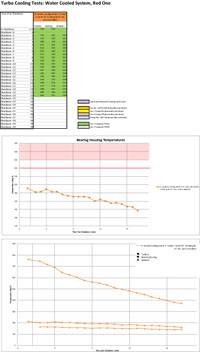
Data set 5 (the latest test configuration) is shown on the summary PDF linked above, and is isolated for ease of reading in AeroVee_Turbo_Liquid_Cooling_Test_Data_Sample-5.pdf. This data shows maximum bearing block temperatures of approximately 211 degrees: a very significant 118 degree drop in maximum bearing block temps from the original AeroVee Turbo configuration and a 60 degree drop in max temps from the air cooled configuration represented in ACV-SB-091616-1B.
Testing Cooling in Cold Weather:
While it’s cold here in Wisconsin at the present time, prolonged high-power static ground runs were conducted and test data shows that turbine housing temperatures were equivalent to temps yielded in September & October 2016 when the Air Cooled system was tested (see AeroVee_Turbo_Air_Cooled_Test_Data_Summary.pdf ) at approximately 600-700 degrees or higher. The aircraft was quickly brought back into the hangar after engine shut-down with an ambient hangar temperature averaging about 52 degrees after closing the hangar door and warming to near 60 degrees as the hangar’s furnace recovered the set thermostat temperature for the building, yielding an almost perfect “standard day” test environment for the cool-down cycle. We plan to continue testing into the spring and summer seasons with warmer temperatures.
The Plan:
After some more testing, including resumption of flight testing (water cooled system has been ground tested only so-far, and ground testing does yield higher engine temperatures with reduced airflow through the cowling), Sonex Aircraft plans to offer this system to the public as soon as possible. A bill of materials will be made available for those wishing to source materials for the modification on their own at the best prices they can find, and Sonex will offer system components at minimal cost to customers. We plan to offer more test data as we collect it, and more details about the system will be offered once it’s ready for release. Subscribe to the AeroVee Turbo Mailing List for Future Updates.
 AeroVee_Turbo_Cooling_System_6255-20.jpg (click to enlarge)
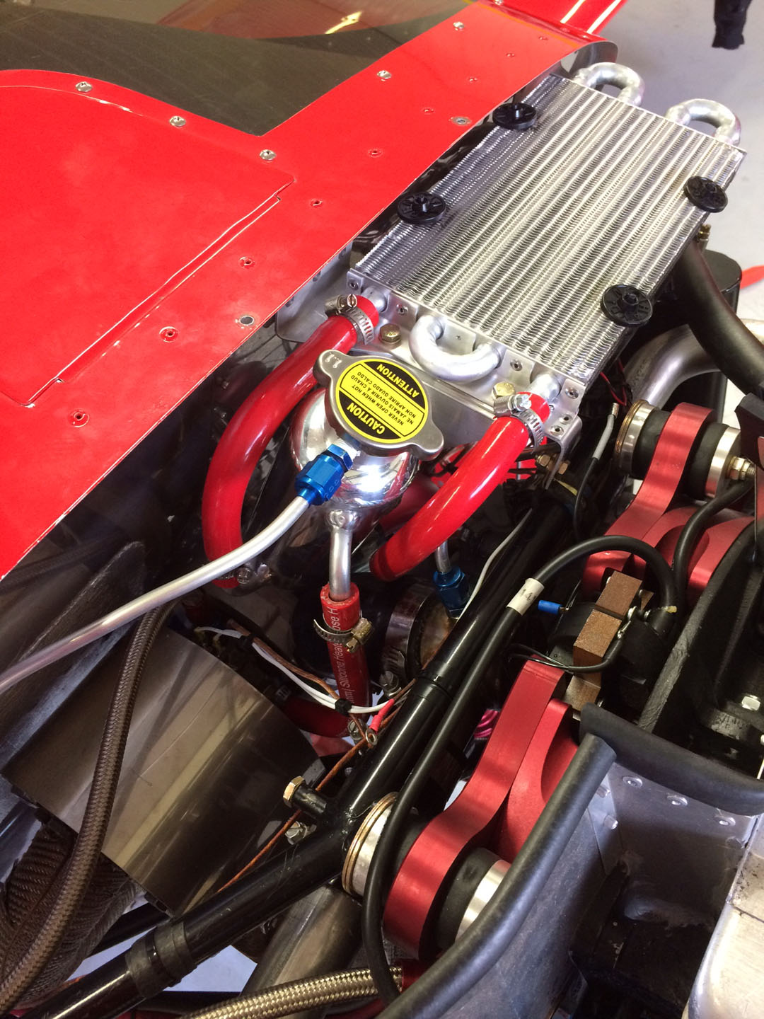 AeroVee_Turbo_Cooling_System_2718.jpg
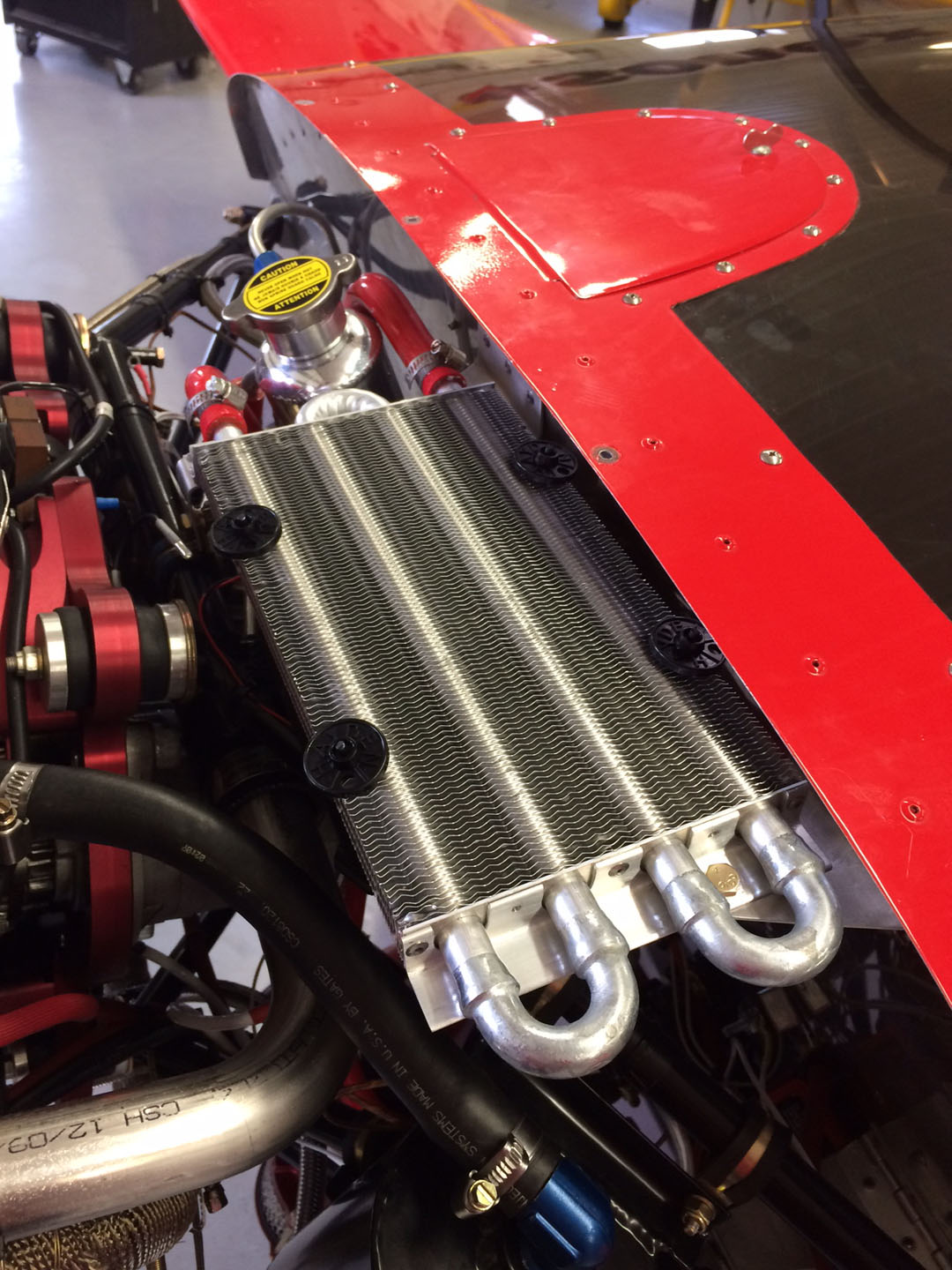 AeroVee_Turbo_Cooling_System_2721.jpg
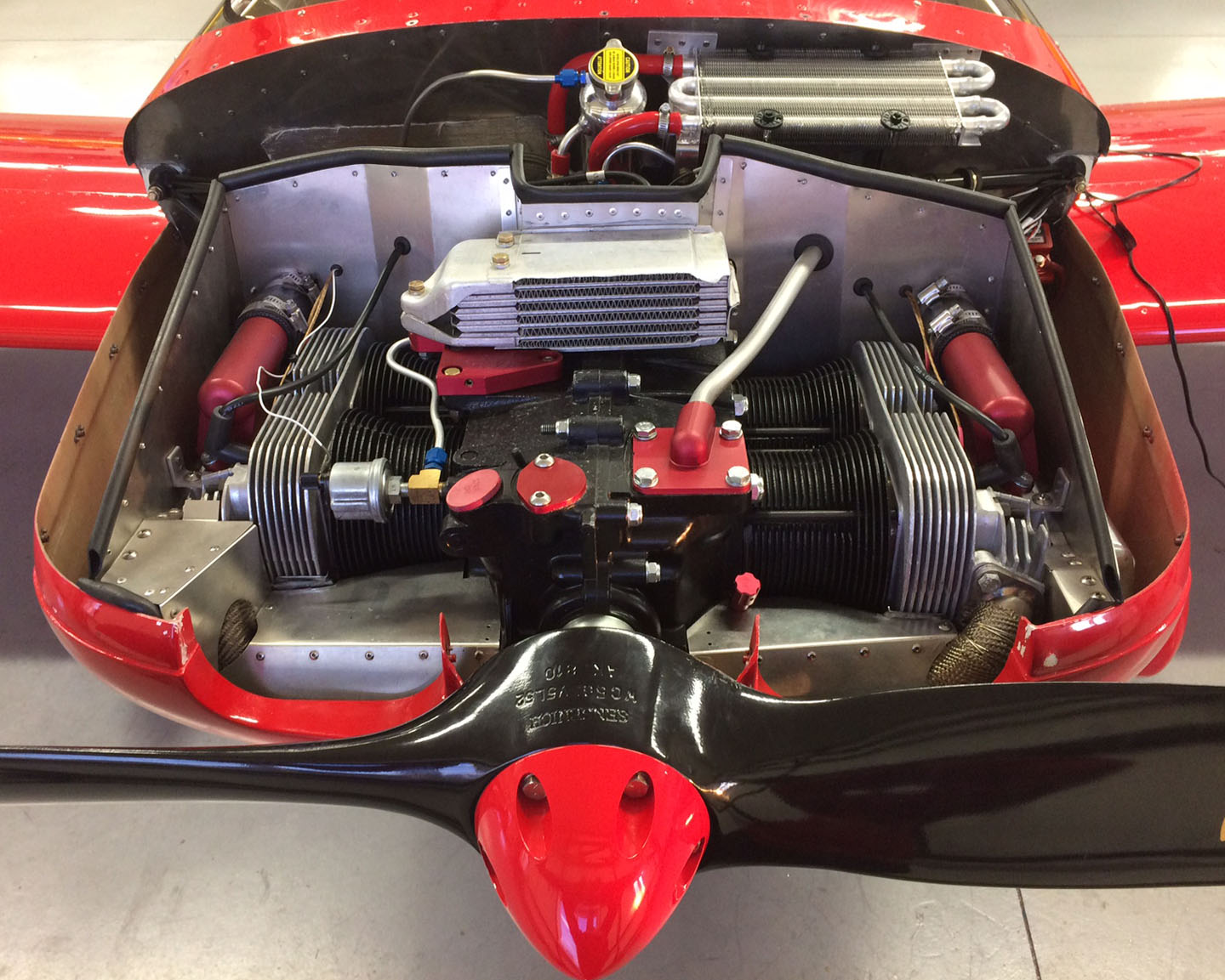 AeroVee_Turbo_Cooling_System_2733.jpg
 AeroVee_Turbo_Cooling_System_2844.jpg